Tuning
Getting Started
ME7 Documentation
The Funktionsrahmen (aka FR):
- http://nefariousmotorsports.com/forum/index.php?topic=400
- http://nefariousmotorsports.com/forum/index.php?topic=1882
Flashing utilities
You need some way to read and write files to the ECU. Some options are:
- The Nefmoto Free ECU Flashing Software and an eBay USB VAG KKL FTDI FT232 based cable (or a CH340 based cable). Does not rely on boot mode, but can also flash bricked ECUs because boot mode was recently added. You can also use (recent) VCDS (Ross-tech) cables with Nefmoto, but you may have to disable "intelligent mode" in the VCDS setup dialog (intelligent mode causes the VCDS driver software to constantly poll the cable in the background, which may interfere with non VCDS apps). For more information, see the Nefmoto Flashing Guide. If you want to use the RossTech cable as a standard OBDII cable on a COM port (not just USB), install RossTech's VCP driver. Make sure you uninstall all of their other drivers first. Also, when you upgrade VCDS, do not let it install drivers over your VCP drivers.
- Galletto 1260 cable and software - Useful in an emergency to recover a bricked ECU. You may have to flash your ECU using boot mode for it to work if your ECU is bricked. However, it may also work w/o bootmode (unlike Galletto 1250).
The most popular combination is a cheap eBay USB VAG KKL cable used with the Nefmoto Free ECU Flashing Software. However, it is good to have Galletto software and cable handy to rescue a "bricked" ECU using boot mode if you can't get the Nefmoto flasher to work in boot mode. It is possible to make most (non-Galletto bundled) FTDI USB based cables work with the Galletto software, but it requires hex editing the executable so that the software looks for[1][2] or alter the serial number stored in the cable using MProg.[3]
One downside to using a boot mode flasher is that it cannot clear the "Error is P0601- Internal Control Module - Memory Checksum error." DTC. You MUST use flashing software that uses the VAG programming protocol, such as the Nefmoto flashing software (not in boot mode), to clear this code.[4] HOWEVER, if you don't currently have this code, boot mode flashing will not cause it, it just won't remove it.
If you plan on doing any flashing, it is strongly recommended to always have a boot mode setup available in case you brick your ECU.
Tuning your ECU
You will need:
- A map editor
- An XDF definition file so that the map editor can locate maps.
- You'll need one specific to the ECU you are using, with a matching P/N. If you wish to use a different version software than your car came with, read this carefully.
- XDF (right click save as) for M-box (most popular).
- A stock binary. Do not start with a modified bin. You have been warned.
- Checksum correction
- Modifying data in the ECU file will invalidate the internal checksum values. These will need to be updated or your car will not start. More info.
- MTX Electronics sells a €10 checksum correction plugin for TunerPro.
- ME7Check is a free executable that will tell you whether the checksums in a file are valid or not. It does not correct them, but if you aren't using WinOLS, you should always use it to check files before flashing them to your ECU.
- ECUFix - $150 - Stand alone checksums correction utility
- ME7Sum - Open source ME7.x checker/corrector. Currently under development!
Logging utilities
- setzi's ME7 Logger (pure awesome) and VisualME7Logger [5][6] (even more awesome)
- Complete guide on how to take and graph logs using ME7Logger - note that this refers to the old "GUI" front end (not recommended), not the newer "VisualME7Logger" frontend linked above (recommended).
- In VisualME7Logger, make sure you enable Options->Log File->Use default log file config_date_time
- If you are logging M-box, there are a bunch of variables that ME7Logger cannot autodetect that you may want to add to your .ecu file - https://github.com/nyetwurk/ME7L/tree/master/ecus
- A list of commonly logged variables is here (lines with a leading semicolon are comments, and thus variables that are not being logged) - https://github.com/nyetwurk/ME7L/blob/master/logs/typical.lst
- Nefmoto logger - more or less equivalent to ME7Logger, but writes out an .xml log file that can't really be used anywhere (yet).
- Ross-Tech's VCDS (aka VAG-COM) - very limited. Useful for reading/clearing DTCs, monitoring fuel trims and misfires, and that's about it.
- APR's ECUx - No longer actively supported by APR. Avoid if at all possible
- A wide-band O2 sensor if you are not using stock fueling. A tailpipe sniffer is fine, as long as you have test-pipes and no pre-cats in your downpipes.
- ECUxPlot to graph logs. Also has a HP/TQ calculator and various other tools.
- Trim Heatmap tool - Plot STFT heatmaps from your ME7Logs to assist tuning KFKHFM!
RS4 K-box logging
There is a bug in the K box file [7] which forces you to connect only once the car is running.
A workaround is to patch these locations:
0x35FD2 - 3D 06 -> CC 00
0x77DE4 - 3D 08 -> CC 00
0x78CB6 - 3D 03 -> CC 00
Terminology
The acronyms are Bosch's Motronic map names from the Funktionsrahmen. If noted, map locations are for the S4 M-box and L-box (8D0907551M and 8D0907551L, 6sp manual and tip, respectively)
Fueling
Always start with this first. If you get fueling wrong, you will likely break something. Get this right, and do not try pushing the envelope in any tables until you are confident your fueling is where you want it. Always use a wideband sensor. Do not skimp on this. The stock narrow bands do not provide you with accurate enough readings. For stage 1-2+, adjusting fueling isn't technically necessary; however, a bit of extra fuel via KFLBTS isn't such a bad idea if you are running pump gas and a bunch of extra boost.
Primary
If you are running a BOV that vents to atmosphere, throw it away. It allows metered air to escape the intake and will cause many unsolvable fueling problems.
If you have a non-stock FPR or fuel injectors:
- KRKTE - Airmass to fuel injector on time conversion based on injector size and fuel pressure (primary fueling)
- TVUB - Injector offset dependent on voltage
A good ballpark starting value for KRKTE is 34.125/(injector flow in cc/min)[8]. If you are using stock injectors and fuel pump, you should not have to touch this. Note that the factor is wrong (should be 0.000111) on many of my old .XDF map packs[9]. For those, you will need to fix the factor so it is 0.000111 and not 0.000167.
The correct factor depends on ME7.x CPU clock frequency.
- 24MHz: 0.0001111
- 32MHz: 0.0001333
- 40MHz: 0.0001666 (rounded to 0.000167 in WinOLS due to precision braindamage)
Fuel density and why the OEM under-scales it
The ME7.5 Funktionsrahmen uses a gasoline density of 0.7135 g/cc (petrol density at 15°C) for the KRKTE calculation, along with a valve correction factor of 1.05 (derived from 0.7135 / 0.6795 ≈ 1.05). The "textbook" density of gasoline is closer to 0.755 g/cc, and you will see that value referenced elsewhere in Bosch documentation.
The OEM appears to have deliberately chosen the lower fuel density for the KRKTE calculation. This is not an error — it serves a specific purpose in the boost control loop.
Using 0.7135 g/cc instead of the "correct" 0.755 g/cc produces a slightly richer KRKTE (more fuel per load percent). When the ECU injects slightly more fuel than strictly necessary, the narrowband O2 correction and fuel trims compensate by reporting slightly less airflow from the MAF. This has a cascading effect:
- KRKTE is slightly rich → more fuel injected per load percent
- MAF compensates → fuel trims pull the MAF reading slightly lower to restore lambda
rl_wreads slightly low → measured engine load is under-scaledps_wsits slightly belowpvdks_w→ estimated manifold pressure stays just under actual pressure
The result: the PID boost controller always sees a small positive error (actual pressure slightly above estimated), rather than oscillating above and below the setpoint. This keeps boost tracking smooth and stable — the PID is always gently chasing, never overshooting and correcting. It also means that if anything drifts, it drifts toward under-boost rather than over-boost, which is the safe direction.
This is worth understanding before you "fix" KRKTE to use the "correct" 0.755 g/cc density. If you do, your MAF scaling will shift, ps_w may end up at or above pvdks_w, and your boost control may become less stable without compensating changes to the VE model (KFURL).
For modified setups, using 0.7135 g/cc is generally the safer starting point — it preserves the OEM's intentional bias toward slightly rich fueling and slightly under-scaled load, both of which are desirable properties when you're pushing more boost than the factory intended.
Note that ethanol has a density of ~0.789 g/cc, so E85 blends are denser than gasoline. If you are running high ethanol content, the "correct" density is higher, but the same principle applies — err toward the lower density for the same safety margin.
MAF Scaling
If you have a non-stock MAF sensor or housing:
- MLHFM - Voltage to MAF conversion based on MAF sensor and housing diameter
- MLOFS - MAF offset. For Bosch MAFs, it should be 200. For Hitachi, 0. Subtracted from the output of MLHFM.
Scale MLHFM (constant throughout scale vs stock!) to get your idle and partial short term fuel trims (STFT) near zero and your WOT AFR to roughly match your requested AFR. Another good MLFHFM sanity check is to log ps_w vs actual boost at WOT - ps_w should generally be slightly below actual boost. If it is over, your MAF is probably overscaled, and if you are running the stock MAP and not a 5120[10] hack, you run the risk of maxing out ps_w, which is a bad thing (see below).
If your MLOFS is non-zero (e.g. most Bosch MAF files), you cannot do a simple arithmetic scaling of MLHFM; you must offset it down (subtract 200) by MLOFS, then scale it, then offset it back (add 200).[11] Alternately, you can set MLOFS to zero and shift MLHFM down accordingly, after which you can scale MLHFM arithmetically as usual. Note that MLOFS takes effect after the CPU takes a moving window average of the output of MLHFM, so technically this operation does not yield a completely identical result as stock.
Note: when you are tuning according to STFT, *make sure* you regularly clear your DTCs to reset the LTFTs to zero, or disable LTFTs altogether using VCDS:
- 099 -> switch basic settings ON -> LR off
Some argue that using a different MAF housing (to extend the functional metered flow range) requires you to fix this so that measured load is "correct". The upside is that all of Motronic's tables that are based on load are probably still good. The downside is that you can't do any fine tuning of regions that are past the end of the axis data, so even if you don't ride the hard MAF limit, you'll run off the end of the load axis in the timing tables (and everywhere else). Some say this isn't so much of an issue. By and large, keeping your max load (at torque peak) under 191 is probably a good idea unless you are prepared to do a lot of remapping to compensate for changing the axis data, or you are ok with not being able to fine tune >191 load regions.
If you do scale your MAF, you may throw a "MAF too high" code. You'll have to increase:
- KFMLDMX - HFM threshhold for B_maxflr diagnosis
- MLMAX - maximum airflow
Finally:
- KFKHFM, FKKVS - fix up individual rich/lean areas, and WOT fueling issues (due to air intake tract and fuel system non-linearities).
In stock files, FKKVS is flat for some reason, and the OEM calibrator decided to fix non-linearities in KFLF. Nevertheless, it is recommended you use FKKVS towards its intended purpose, and leave KFLF alone (ps_w limit hack note below notwithstanding).
The downside to attempting to add fueling via KFKHFM is that ps_w might cap out, and further additions to KFKHFM will have no effect. Even worse, if you are running a very high power setup, and your MAF is properly scaled, even a stock KFKHFM might result in a ps_w cap (in addition to maxing out load). One possible workaround is to underscale KFKHFM in those regions, and make approprate balancing changes in KFLF. Of course, to make KFLF's changes line up proplery with KFKHFM, you will have to make sure both maps have the same axis data in the applicable regions.[12]
Note that KFLF's description as "lambda" is a misnomer. It is not lambda at all. It is an injector on time scaling table where larger numbers are longer injector time, smaller numbers are shorter injector time.
Also, you should always compare msdk_w (alpha-n estimated air flow) vs mshfm_w (measured airflow). If they are different, the car will run poorly if the MAF fails or is unplugged. See the alpha-n calibration section below for how to fix this.
Alpha-N calibration
WDKUGDN — what it actually is
WDKUGDN is a 1D Kennlinie (RPM → throttle angle °) that defines the choked flow point of the throttle body at each RPM.
The physics: air flowing through a restriction (the throttle plate) accelerates as the opening narrows. At a critical pressure ratio — when downstream pressure drops below ~52.8% of upstream pressure — the air velocity reaches the local speed of sound and the flow is choked. At this point, opening the throttle further does not increase airflow. The only way to increase flow past choke is to increase upstream pressure (i.e., boost).
WDKUGDN stores the throttle angle at which this choke condition occurs for each RPM. Below this angle, the throttle plate is the bottleneck — the ECU uses throttle position to control load. Above this angle, the throttle body is wide open enough that it's no longer restricting airflow — the turbo and wastegate take over load control.
Specifically, when wdkba >= WDKUGDN(nmot):
B_ugdsis set (true = "unthrottled operation")- The ECU stops using the throttle for load control and hands off to the wastegate
- Fuel adaptation (FUEREG) is disabled
- The throttle enters the Ueberweg (bypass) range — linear interpolation to 100%
This is a physical property of the throttle body and engine displacement. It is not a tuning parameter. It should only be changed if you physically change the throttle body bore diameter or engine displacement.
Do NOT adjust WDKUGDN for alpha-n
The common advice ("compare msdk_w vs mshfm_w, adjust WDKUGDN until they match") is wrong. WDKUGDN defines when the throttle chokes — it does not define how much air flows at a given angle. Changing it to fix an msdk_w vs mshfm_w discrepancy causes:
B_ugdsfires at the wrong angle. Every downstream system that checks this flag — throttle control mode, fuel adaptation, boost control handoff — makes the wrong decision.- Fuel adaptation (FUEREG) disables at the wrong throttle angle. Too low and you lose closed-loop fueling where the MAF is still the primary signal. Too high and FUEREG stays active into boost.
- The Ueberweg calculation produces wrong values. The bypass interpolation between WDKUGDN and 100% throttle uses WDKUGDN as its breakpoint. Move it and the entire KFVPDKSD pressure-ratio transition zone (the region >0.95) is wrong.
- The actual problem is still there. You've masked where the error is visible by changing when the ECU switches between load calculation modes. The VE model is still wrong and the error reappears under different conditions.
The correct maps to calibrate for alpha-n
| Priority | Map | When to Change | What It Does |
|---|---|---|---|
| 1 | KFMSNWDK | Changed throttle body or intake manifold | Throttle body flow map (angle × pressure ratio → normalized mass flow). The single most important map for alpha-n accuracy. |
| 2 | KFURL | Changed cams, head work, port work | VE slope (%/hPa per RPM) — how much load each hPa of pressure produces |
| 2 | KFPBRK | Changed cams, head porting, compression ratio | Volumetric efficiency correction factor (RPM × load → factor) |
| 2 | KFPRG | Changed cam timing, exhaust, turbo | Residual gas partial pressure — the manifold pressure at which cylinder filling = 0 |
| 3 | Adaptation reset | After ANY map changes | Clear msndko_w (additive offset) and fkmsdk_w (multiplicative factor), then drive with MAF connected to re-learn |
| 4 | KUMSRL | Changed engine displacement | Mass flow → load conversion constant |
Diagnostic — match the error pattern to the map:
| Symptom | Likely Map |
|---|---|
| Load error proportional to pressure (grows linearly) | KFURL — VE slope is wrong |
| Constant load offset at each RPM (independent of pressure) | KFPRG — residual gas offset is wrong |
| Non-linear load error (varies with both RPM and load) | KFPBRK — VE correction factor wrong at specific operating points |
| Error varies with intake air temperature | FWFTBRTA — temperature weighting is off |
The msdk_w computation chain (from BGMSZS in the Funktionsrahmen):
msdk_w = (KFMSNWDK(wdkba, pspvdk) + msndko_w + msnlls_w) × fpvdk × ftvdk × KLAF(pspvdk) × fkmsdk_w
Where msndko_w and fkmsdk_w are learned adaptation values that freeze when the MAF is unplugged. If the underlying maps (KFMSNWDK, KFURL, KFPBRK, KFPRG) are correct and the adaptations were learned with MAF connected, alpha-n will be accurate.
Changing fuel injectors does NOT require alpha-n recalibration. Injectors affect fueling (KRKTE/TVUB), not air measurement. However, reset adaptations after injector changes since O2 adaptation may shift the learned values.
Finally, periodically check long and short term fuel trims (LTFT/STFT) from VCDS group 32/33. They can also be logged directly via rkat/fra/fr/usvk:
LTFT:
Group 032: 001F (rkat_w), 0021 (fra_w), 0020 (rkat2_w), 0022 (fra2_w)
STFT:
Group 033: 001C (fr_2), 0025 (usvk ), 001D (fr2_w), 0026 (usvk2 )
Note that since ME7 only has narrow band O2 sensors, LTFT/STFTs can only tell you if your fueling is accurate while lambda request is 1 (AFR 14.7). To check WOT fueling you must have 3rd party wide band sensors installed.
Idle LTFT and idle misfires
If you have idle problems (and/or idle LTFTs you can't seem to zero out), you may have to investigate tuning for your injector latency and/or idle injection period.[13][14]
- TVUB - Injection time offset (compensate for injector latency)
- FKKVS - Correction factor for fuel supply system
IMPORTANT: If you decide to tune TVUB empirically via idle STFTs, make sure your partial throttle STFTs and WOT fueling is right first, or you'll just have to start all over again once you have KRKTE and your MAF scaling set up right.
According to Bosch documentation, FKKVS is for compensating for pulses in returnless fuel system. However, it can also be used when TVUB isn't enough to correct for non-linear injectors (or other non-linearity in the fuel system).
If you are running really big injectors, and you are running rich no matter how much you turn down KRKTE, you may need to reduce the minimum injector on time. Some injectors run best with a slightly higher TEMIN (e.g. EV14[15]), but most very large injectors require a smaller TEMIN.
- TEMIN/TEMINVA - minimum injector on time
If you did not properly scale your MAF, and you are getting a rough idle but aren't seeing idle misfires, it could be because your load at idle is too low, inhibiting misfire detection. Scale your MAF properly, or decrease your misfire recognition load threshold.
- RLSALUN - Load threshold for shear detection for suppression of misfire detection
- RLSALULL - Load threshold for shear detection for suppression of misfire detection during idle
Finally, if none of this works, you may have to increase your idle RPM and/or idle torque reserve (alters idle timing)
- NLLM - idle RPM
- NFSM - idle RPM while in gear
- KFMRES - idle torque reserve
- KFMRESK - idle torque reserve while transmission decoupled (clutch in)
If your car runs poorly while it is warming up (engine temps less than 85C-90C), you will want to tweak the warm up enrichment tables according to your STFTs (Note that a wideband sensor might be misleading here since during warmup, closed loop lambda may interfere with proper fueling and overcompensate):[16][17]
- KFFWL_0_A
- KFFWL_1_A
You can bump the idle/cold start RPM as well:
- KFNLLKHM - Elevated idle RPM until motor is warm
- KFNLLNST - Start RPM (momentary)
Wall wetting during warmup is also an issue, especially for very large injectors or injectors with spray patterns that deviate from stock:
- WFRL
- KFBAKL, KFVAKL
Open loop AFR
When requested lambda is <1 (richer than stoichiometric), the fueling system will go "open loop". This means that the ECU will no longer use the narrow band O2 sensors to regulate fueling in closed loop (feedback). It will use ONLY the MAF signal to guess how much fuel should be added to the mix based on how much airmass is being detected in the intake.
There are three ways to adjust WOT (open loop) requested AFR
- LAMFAW: enrichment based on pedal position (requested torque from KFPED)
- LAMFAWKR: enrichment based on knock recognition
- LAMBTS: enrichment triggered by calculated EGTS passing a threshold
Final requested AFR will follow the richest set point of the three components.
LAMFAW
Driver requested AFR:
- LAMFA - requested lambda. Not very flexible for high load enrichment, uses requested torque instead of actual torque. Also, the stock LAMFA torque axis is (incorrectly) restricted to 0.5%-1.0% on 2.7t ECUs. You will have to change it to full range (multiply each value by 100 to result in 50%-100%) to use LAMFA, otherwise, the 1% column will be used at ALL requested torque points![18]
- ZKLAMFAW/ZKWLAFWL (0x1C3EE) - time constant for driver requested lambda filtering. This filter smooths LAMFA. Unfortunately, the smoothing has the side effect of delaying the effects of LAMFA.[19] You may want to bring in LAMFA fairly aggressively and/or increase ZKLAMFAW significantly to compensate.[20]
- TLAFA - time delay before driver requested lambda active. Already set to 0 on many files. On others, you may have to reduce it to get LAMFA to take effect in a timely manner.
The result is "lamfa_w"
LAMFAWKR
Knock recognition based enrichment:
- CWLAMFAW - when bit zero is set to 0, don't allow dzwwl to advance dzwlamfaw. If you leave bit zero set to 1, dzwlamfaw will likely stay near zero at IAT's below 39C (102F) (since DZWWL can counteract WKRMA), and you won't get much knock based enrichment, since dzwlamfaw is the timing input to KFLAMKRL[21].
If you leave CWLAMFAW stock, you may need to adjust a few tables to prevent dzwwl from counteracting wkrma.
- KFZWWLRL - inputs are: rl, tmot (coolant temp)
- FZWWLRLN - inputs are: rl, nmot
- KFZWWLNM - inputs are: nmot, tans (iat)
The output of these tables is dzwwl:
dzwlamfaw is then
| CWLAMFAW bit zero | dzwlamfaw |
|---|---|
| 0 | |
| 1 |
Note that min(0, dzwwl) prevents dzwwl from being greater than zero when CWLAMFAW bit 0 is 0
dzwlamfaw is then fed into:
- KFLAMKRL - enrichment based on load and dzwlamfaw
- DLAMTANS - additive correction to KFLAMKRL based on intake temp
- KFLAMKR - enrichment correction factor based on rpm and load
They are combined like this:
The result is "lamfawkr"
LAMBTS
EGT enrichment tables:
- KFLBTS_0_A - requested lambda for component protection when calculated EGT (
tabgbts_w) is above TABGBTS, modified by FBSTABGM, DLBTS, and KFFDLBTS.
- FBSTABGM (0x150C2) - KFLBTS multiplier. Make sure you change the axis properly to represent your lowered TABGBTS. Again, not necessary if you have a properly scaled MAF. Also, all ones in most files.
- [KF]DLBTS and KFFDLBTS -
lambts = KFLBTS + [KF]DLBTS*KFFDLBTS. Therefore, setting KFLBTS to 1 where you don't need it won't disable bts, you also have to set KFFDLBTS = 0 as well.[23] Note that Mbox has DLBTS (2D), not KFDLBTS (3D).[24]
- TABGBTS - Threshold for KFLBTS. Unless calculated EGTs are above this threshold, KFLBTS is ignored. You may have to lower TABGBTS if you have a scaled MAF, since calculated EGTs will be artificially low.
The result is "lambts"
Result
The lowest value of the three (lamfa_w, lamfawkr, lambts) become your requested AFR.
Thus, you can use the combination of LAMFA, BTS, and KFLAMKR to tailor your AFR. In particular, pre-emptive rich fueling at low actual loads (but high requested load) may inhibit knock sooner than the KR approach. You can use BTS to do further enrichment when EGTs get dangerously high, unless you have BTS activate at very low actual loads (and/or calculated EGTs). The latter may be undesirable for fuel economy reasons; it is more fuel efficient to have BTS activate much later, let LAMFA handle pre-emptive, high load request (but low actual load) enrichment, and let KR handle real time knock inhibition.
Note that on tunes for low octane gasoline, it is likely that your target AFR is so low (to prevent knock) that additional BTS fueling is unlikely to protect against anything, unless your fuel system is severely under-delivering fuel do to injector/fpr/fuel pump malfunction.
Part throttle LTFT
Once you get your WOT AFR right, you may notice that your LTFTs are way out of whack. If they get too far out, you'll throw a code and possibly go into limp mode.
- KFKHFM - Correction map for MAF. Log STFTs at various part throttle positions, RPMs, inclines, and gears to determine where the MAF readings need tweaking. If you are using the stock MAF and intake system, you should not have to touch this.
You can also do fueling corrections in both FKKVS and KFLF, depending on preference.
Once you have got both partial throttle and WOT exactly where you want them, go back and clean up TVUB according to your idle STFTs/LTFTs as needed.
You may also simply want to disable LTFTs while you are fine tuning part/idle throttle. Make sure you restore it to stock when you are done tuning.
Use this Trim Heatmap tool to show what adjustments in KFKHFM should be made to correct for any intake changes. Note this assumes your fueling is stock or perfectly tuned. It is only meant to tune KFKHFM once your KRKTE and TVUB are set up correctly. The more data you have, the more accurate it will be.
Consumption
Now that you have your fueling set up, you'll probably notice that your MPG readings in your cluster are totally wrong. Fill up a with a tank of gas, and reset your trip odometer and average MPG. When you are done with the tank, fill up your tank, see how much gas you used and how far you went, and check it against the new average MPG. Get a calculator out, and correct it here:
- KVB - fuel consumption (MPG in cluster)
Standard KVB value can go only up to 776cc injector size due to reaching the maximum value it accepts.
To accommodate injectors larger than that you have to also change
- FKVA (0x1A4D5) - Constant conversion factor for consumption display[27]
This is a multiplier for KVB.
For reference, you may be able to derive the right value using this (although some find trial and error tweaking is much easier):
Boost
Never use an MBC or EBC. If you don't properly tune boost request and the PID, the deviation between expected and actual boost can cause problems if the N75 is not controlling the WG.
If you have an MBC or EBC, throw it away. If you are reading this, you will be tuning for exclusively N75 control anyway.
Load to boost conversion
ME7.1 doesn't really have a "boost" table. It does everything based on "specified load".
Approximation
Keep in mind, this is a rough approximation. It can be off by as much as 30% or more. It is dependent on a large number of factors including air density, temperature, elevation, and the alignment of the stars and the moon. Use this formula to get close, then adjust based on real world observations.
requested boost=10*(LDRXN)+300mbar
Where requested boost is in absolute pressure, and absolute pressure is the pressure of the air charge including barometric pressure.
Example:
LDRXN=195
10*195=1950
1950+300=2250
Where 2250 is the absolute pressure in millibars.
To determine manifold pressure subtract the barometric pressure. Sea level = 1 Bar = 1000 mBar.
2250-1000 = 1250 mBar
1250 mBar = 1.25 Bar
1 Bar = 14.7 psi
1.25 Bar * 14.7 psi/Bar = ~18 psi
Where 18 is psi in manifold pressure.
Actual rlsol to plsol calculation
Converting from load to pressure is primarily a function of fupsrl (100% load is 1 bar at standard temp and humidity, assuming a VE of 1) and tans (mass density is dependent on temperature).
Roughly, this corresponds to:
plsol = (rlsol + rfagr) / fupsrl / fpbrkds / vpsspls
Where
rfagris the amount of airmass displaced by the residual pressure leftover from the last cyclefupsrlis the 100% load -> 1 bar conversion (dependent ontans)fpbrkdsis the pumping correction based on VEvpssplsis the pressure drop across the throttle plate
The actual calculation is pretty complex; there many other correction factors involved..
According to the FR, assuming SY_BDE is false, and SY_AGR is true:
rfagr
rfagr is the air mass displaced by the pressure of the gases in the combustion leftover from the (presumably partially incomplete) exhaust stroke
pirg = fho * KFPRG
   fho = pu/1013
   KFPRG = ~70
fpbrkds corrects for VE (dependent on RPM and cam timing). It is used here to calculate rfagr and later as a correction to pssol
fpbrkds = ~1.016 (from KFPBRK/KFPBRKNW)
pbr = ps * fpbrkds
psagr = 250 (?)
rfagr = MAX(pbr-pirg,0)*fupsrl * psagr/ps
fupsrl
fupsrl is where most of the magic happens: it is the most basic conversion between load and pressure. Note that it is approximately 0.10, where 100 load => 1000mbar.
fupsrl = KFURL * ftbr
   KFURL = ~0.1037
ftbr
ftbr corrects the pressure based on temperature (i.e. for a given specified load, you need more pressure for an equivalent airmass at an increased temp). It is based on evtmod and fwft
evtmod is the modeled combustion chamber temperature, based on tans (intake air temp) and tmot (coolant temp). The idea is the the combustion chamber temp is basically the intake air temp heated by the engine block. In most cases, evtmod will be very very close to tans.
evtmod = tans + (tmot - tans) * KFFWTBR
   KFFWTBR = ~0.02
fwft is a correction factor that can be applied to ftbr according to FWFTBRTA
fwft = FWFTBRTA(tans)
   FWTFTBRTA(tans) = (tans+673.425)/731.334 (linear fit to stock FWFTBRTA)
ftbr's relationship to evtmod (from tans) and fwft is fixed and cannot be altered other than in the code itself:
ftbr = 273/(evtmod+273) * fwft
In theory, one could construct FWFTBRTA such that ftbr is flat with respect to tans (after being corrected by fwft), if you want to use a flat LDIATA and KFTARX with no side effects.
pssol
Moving on, now we can calculate desired manifold pressure pssol:
pssol = (MAX(rlsol-rlr,0) + rfagr + rlr)/fupsrl/fpbrkds
Note that rlr cancels itself out, aside from the initial MAX(rlsol-rlr,0) contribution, so its calculation is omitted here for brevity (assuming we only care about regions where rlsol>=rlr), yielding:
pssol = (rlsol + rfagr)/fupsrl/fpbrkds
plsol
The final step is to calculate desired pressure upstream of the throttle body. plsol:
vpsspls corrects for the pressure drop over the throttle plate
plsol = pssol/vpsspls
   vpsspls = ~1.016 (from KFVPDKSD/KFVPDKSDSE)
And we end up with
plsol = (rlsol + rfagr) / fupsrl / fpbrkds / vpsspls
ps_w
ps_w is modeled pressure based on load (rl_w) calculated from MAF and RPM.
The rl_w to ps_w conversion basically follows the rlsol to plsol conversion, but uses rl_w instead of rlsol to calculate ps_w.
ps_w = (rl_w + rfagr) / fupsrl / fpbrkds / vpsspls
rl from ps
The reverse relation converts ps into rl:
rl = (ps * fupsrl * fpbrkds * vpsspls) - rfagr
Specifying requested boost
First, make sure the 80-100% torque request (misopl1=milsol/etazwbm/etalab) rows request enough load:
- KFMIRL - specified load
- KFMIOP - converts
rlmax(from LDRXN) into the torque request cap, which limits the torque request input to KFMIRL
Note that milsol will be limited by the output of KFMIOP (where the load input is rlmax), and the stock values of KFMIOP never exceed 89%. This means that unless you alter the max values of KFMIOP (no, there is no reason to do this), the largest torque request KFMIRL will see is 89%. Tune KFMIRL (not KFMIOP) accordingly.
Specified load/boost will never exceed these limits (whichever is lower):
- LDRXN - maximum specified load
- KFLDHBN - maximum requested pressure ratio
Specifically, on a full throttle pull, your boost profile will follow LDRXN or KFLDHBN, whichever results in a lower requested load.
If it does not follow LDRXN, requested load may be getting limited by ldrlts_w (ChargeLimitTurboProtection), which comes from KFLDHBN (after being converted from pressure ratio, to absolute pressure, to load). That said, you may intentionally use KFLDHBN to limit (and thus determine) boost request by moving LDRXN out of the way and up, such rlmax is higher than ldrlts_w. Some find this more intuitive, since the resulting boost is independent of IAT and VVT angle. The OEM tune only relies on rlmax (instead of ldrlts_w) to determine boost request so that the torque response is more consistent (since this method compensates for IAT and VVT).[28]
K03s and K04s have some severe flow limitations, so unlike big turbos, you will want your boost to taper (not ramp up) to redline. ECUxPlot has a pressure ratio/flow plotter that you can use to compare against your turbo's compressor map.
You will throw a 17963 Charge pressure: Maximum limit exceeded code if your boost deviation is too high:
- KFDLULS - Delta pressure for overboost protection
You should never have to change this; if you are throwing charge pressure codes, your PID is set up very wrong.
If you screw up, it is possible that specified boost is higher than the maximum possible measured boost. For obvious reasons, the PID will not like this. To prevent this, set this to zero (or between 0 and -9):
- DSLOFS - MAP pressure sensor offset
Absolute maximum measured boost is 0xffff/25.6 = 2559.96 mBar (DSLOFS = 0), and 2543.55 mBar (DSLOFS=-16.40646)
Maximum spec boost is 0xff*10 = 2550 mBar
Note that 2550 > 2543.55!
These are both hard ECU limits, and cannot be increased by simply changing sensors or internal ECU MAP scaling.
If you plan to run closed loop boost (PID control) near the sensor limit, set DSLOFS to 0 unless you are 100% sure your requested boost will never exceed the sensor maximum.
If you are planning to run open loop boost (locked WGDC via KFLDRL) keep it stock. This will guarantee the PID always runs maxed out.
Note that if you do plan to run closed loop near 2.5 Bar, you are much better off getting a larger pressure sensor and running the 5120 hack.
Boost (rlsol) intervention via rlmax
As mentioned before, driver requested load rlsol (aka ECUx "EngineLoadRequested") from KFPED/KFMIRL etc. is capped by rlmax_w (aka ECUx "EngineLoadCorrected") which comes from LDRXN via rlmx_w (aka ECUx "EngineLoadSpecified").
However, there are many things which cause rlmax to not follow rlmx from LDRXN.
- Intake air temperature via
frxta - Motor (coolant) temperature via
frxt - Knock recognition via
fldrrx_w - LDPBN via
ldrlms(aka ECUx "ChargeLimitEngineProtection") whenB_brlmxis set (Coolant temp protection) - LDORXN via
E_ldo(LDO DTC)
But most notably
- KFLDHBN via
ldrlts(aka ECUx "ChargeLimitTurboProtection")
If you see rlmax_w following ldrlts_w instead of rlmx_w, it means KFLDHBN is limiting boost, not LDRXN.
In summary, rl_max is the minimum of:
rlmxko_wfrom LDRXN->rlmx_wcorrected bytans(IAT),tmot(coolant temp), and KRldrlts_wfrom KFLDHBNldrlms_wfrom LDPBN whenB_brlmxis set- LDORXN: when
E_ldois set
To help diagnose, log these:
rlsol"EngineLoadRequested"rlmax_w"EngineLoadCorrected" (this is a misomer, it should be something like "LoadLimitCorrected")rlmx_w"EngineLoadSpecified" (this is a misnomer, it should be "LoadLimitSpecified")ldrlms"ChargeLimitEngineProtection"ldrlts"ChargeLimitTurboProtection"
IAT effect on specified load and requested boost
The OEM philosophy
The stock OEM calibration is designed to make the same ~250hp in every weather condition — 0°C winter mornings and 40°C summer afternoons alike. It does this by increasing boost when it's hot (to compensate for lower air density) and reducing load limits when IATs climb too high (to prevent knock). The result is a car that feels the same year-round. Consistent, predictable, and leaving a lot of power on the table when conditions are favorable.
You likely want the opposite philosophy: take advantage of cold air by allowing more boost and timing advance (cold, dense air is far less knock-prone), and protect the engine in hot air by reducing boost and timing before knock becomes a problem. A properly calibrated IAT strategy can safely make 10-15% more power on a cold day compared to a tune that ignores air temperature — power that the stock mapping deliberately throws away in the name of consistency.
How ME7.1 handles IATs
ME7.1 corrects both specified load and requested boost based on IAT (tans):
Load limiting via KFTARX:
Specified load max (rlmx) is corrected via KFTARX, producing rlmxko_w, which caps requested load (rlsol) via rlmax. In the stock calibration, KFTARX pulls load as IATs rise to prevent knock.
- KFTARX - IAT correction for maximum specified load
Boost scaling via ftbr:
For a given requested load, ME7.1 automatically scales requested boost via ftbr as IATs change. Hot air is less dense, so the ECU requests more pressure to achieve the same cylinder fill. This is the mechanism that keeps the car feeling the same in hot weather — it's requesting more boost to compensate for the lower density air, which is exactly what you don't want when you're already near the hardware limits.
- FWFTBRTA - IAT correction to
ftbr
LDIATA compensates for these IAT corrections in the PID, so that the wastegate duty cycle adjusts properly for the changing boost target.
- LDIATA - LDR I-Regulator limit as a function of IAT
Tuning strategy
Cold air (low IATs): This is where your power lives. Cold, dense air resists knock better and packs more oxygen per unit volume. You want KFTARX to allow full (or even increased) load at low IATs. The stock KFTARX is conservative here — it leaves headroom that you can claim. If you have knock margin (monitor dwkrz), you can also advance timing via KFZW at high load points when IATs are low.
Hot air (high IATs): This is where you protect the engine. As IATs climb, you want KFTARX to taper load downward — not to keep power consistent as the OEM does, but to keep the engine safe. Hot air is knock-prone, and the combination of high boost + high IAT + pump gas is where engines break. A sensible taper in KFTARX across rising IATs keeps requested boost from exceeding what the engine can safely handle.
The ftbr trap: Even with a perfectly flat KFTARX and LDIATA, you will still see more requested boost as IATs rise because ftbr automatically increases the pressure-to-load ratio. This is the ECU's density compensation — it "knows" hot air is less dense and requests more pressure to hit the same load. If you are running enough boost that this density compensation could push requested boost anywhere near your MAP sensor ceiling, you should not be running a stock MAP sensor. Use a binary with the 5120 hack implemented and a MAP sensor with appropriate pressure limits for your setup (3 bar, 4 bar, etc.). Running closed-loop boost control near the sensor ceiling is asking for PID divergence — the integrator will wind up chasing a setpoint it can never measure. Size your MAP sensor for your boost target plus the IAT-driven ftbr overhead, and this is a non-issue.
With a properly sized MAP sensor, taper KFTARX downward as IATs rise to keep load requests safe, and make sure LDIATA reflects those changes. Alternately, you can construct FWFTBRTA values that cancel out the fixed ftbr correction entirely.
Note that IATs do not affect ldrlts (from KFLDHBN) in the same way they scale rlmax — the IAT correction is already accounted for when converting the pressure ratio from KFLDHBN into ldrlts. Also note that the IAT correction applied when converting load to boost is reversed when converting back — the corrections cancel out in the round-trip.
Cam changeover effect on requested boost
Motronic likes to change requested boost depending on cam position. While it may seem like a good idea in theory, in practice, abrupt changes in requested boost near the MAP limit can make the boost PID unhappy. When logging, you may see an odd notch in requested boost between 3000 and 4000 RPM. These maps are what is causing that notch
- KFPBRK - Correction factor for combustion chamber pressure
- KFPBRKNW - Correction factor for combustion chamber pressure when NWS active
- KFPRG - Internal exhaust partial pressure dependent on cam adjustment when sumode=0
- KFURL - Conversion constant for ps->rl dependent on cam adjustment when sumode=0
It is not recommended you change these unless you know what you are doing and there is no other way to get the PID to behave.
Alternately, you can move the cam position change up past the peak boost area (via KFNW and KFNWWL), which you probably should do anyway if you have larger turbos that spool slower.
Finally, you can just use KFLDHBN to limit boost request instead of LDRXN. This method is not affected by VVT.
Base boost and wastegate spring pressure
With aftermarket and/or tighter wastegates, you may experience bucking and choppy throttle response in part throttle near waste gate cracking pressure[29]. The throttle angle desired is dependent on the boost pressure in a turbo car since after a certain angle, throttling losses are negligible and it is better to hold the throttle wide open. But if the turbo cannot be controlled at that boost pressure via waste gate control any longer (because the wastegate no longer can open at that pressure), the ECU needs to be told to continue to use the throttle (and not go WOT) up to the new, higher boost pressure to regulate torque instead.
To correctly determine how much throttle opening is required to produce the amount of torque requested and prevent the ECU from going WOT prematurely, a few maps have to be tweaked in the module LDRPLS to set the base boost pressure in the ECU. The maps that set base boost are:
- KFVPDKSD - Target pressure ratio in dynamic operation
- KFVPDKSE - Target pressure ratio in steady state operation
The axes of these maps are nmot (engine speed) and vpssplg_w (requested pressure ratio) and the Z-values are pressure ratio across the throttle body. Look for the values in the table that start to exceed the threshold of PSPVDKUG (generally 0.95) and approach 1.0, and trace up to the vpssplg_w axis. The pressure ratio minus 1 bar at this column (when stock) should be your wastegate pressure (3-6psi for stock wastegates).
An easy way to make an initial pass is by only modifying the vpssplg_w axis data. Take the ratio of the new pressure to the stock wastegate pressure (e.g. 1.8/1.3 = 1.38), and correct the vpssplg_w axis by multiplying each value by this ratio. This roughly sets base boost for proper throttle control. You can further tune this table by making sure areas below the spring/cracking pressure of the wastegates stays below the value in PSPVDKUG.
Additionally, WDKUGDN determines the "base" throttle plate angle corresponding to where the result of KFVPDKSD/E is .95 - that is to say, where to cap the throttle plate to control flow below the wastegate spring/cracking pressure. As KFVPDKSD/E approach 1.0, this throttle plate angle cap will increase, until the requested pressure ratio is above the spring/cracking pressure.
LDRPLS works in conjunction with FUEDK to determine throttle plate angle. After getting base boost situated in LDRPLS, FUEDK determines throttle plate angle via a map that utilizes airflow and throttle plate angle. This map is
- KFWDKMSN - Mapping for throttle target angle
and its inverse
- KFMSNWDK - Normalized airflow over throttle plate
You should not have to adjust either of these unless you made radical throttle body changes.
Note that there are two variants of 'base boost' according to CWPLGU (compile time option, not a map). One is ambient pressure (most common, like S4), the other is wastegate pressure (e.g. RS4).
Boost PID
If your actual boost is not meeting requested boost, you may have to increase the PID I limit for 850 and 1000mBar. In general, you want KFLDIMX to follow what you expect your WGDC to be in the steady state, so after peak boost, you should set this to where you want the WGDC to settle. Note that PID trims (I-Regulation adaptation) may alter this limit. It should also roughly follow the profile of requested boost when it is tracking LDRXN. That is to say, if you have a flat max (WOT) boost request, you should have a flat KFLDIMX. The reason IMX is so important in ME7 is that in the steady state, P result is near zero and D is scheduled out with B_lddy. This means that I dominates.
On a WOT pull, I is maxed out due to integrator windup (accumulated error) so it is simply following IMX.
- KFLDIMX - LDR I-Regulator limit. The x-axis input is relative requested pressure (
plsolr_w) in hPa (same as mBar), which, in the M-Box, is "requested absolute pressure (plsol_w)" - "ambient pressure (pu_w)".
Along with KFTARX, there is another IAT correction that ME7.1 uses to allow the PID to add waste-gate duty cycle at elevated IATs. If you altered KFTARX you should compensate for those corrections here (but note that a completely flat KFTARX will still result in a requested boost that increases with IAT):
- LDIATA - LDR I-Regulator limit as a function of IAT
If you aren't using K03s, you may have to tweak the PID response. Note: this is not used to adjust requested boost. It is used to compensate for different waste-gate responses.
- KFLDRL - Map for linearization of boost pressure = f(TV). This is the post-PID waste-gate duty correction table. The result of the PID (
ldtvr_w) is the input to this map. The actual DC (ldtv) is the output of this map. All of the results of the PID end up in this table to be linearized. That is to say, if you have a flat WGDC (with respect to RPM) going into KFLDRL (ldtvr_w), the result [b]should be[/b] a flat actual boost (with respect to RPM) - most likely requiring a rising post-linldtv, and thus a rising KFLDRL for a given inputldtvr_w. Calibrating this correctly is time consuming, but worth the effort.[30]
PID scheduling
- LDRQ0 - LDR PID Q0 in dynamic operation (proportional term) - likely leave this alone, log
ldptv - LDRQ0S - LDR PID Q0 in static operation (proportional term) - likely leave this alone
- LDRQ1ST - LDR PID Q1 in static operation (integral term) - likely leave this alone, log
lditv_w,ldimx_w - KFLDRQ2 - LDR PID Q2 (differential term) - adjust this to compensate for overshoot when your boost ramp meets requested. If you have overshoot, try decreasing KFLDIMX first. If you have undershoot, try increasing KFLDIMX first. Only change Q2 as a last resort. Log
ldrdtv
The x-axis pressure input to the PID terms are all lde ("actual absolute pressure" - "requested pressure")
KFLDRL can also be used to get open-loop type behavior for operation past the MAP and requested boost limit by making the output duty cycle unresponsive (flat) to uncorrected duty cycle (from the PID) at various RPM/DC points. Again, if you do this, make sure to leave DSLOFS at the stock value. This way, requested boost will always be higher than measured boost, and you will stay in open loop control.
One undesirable side effect to leaving DSLOFS stock (and requesting more boost than the MAP can read) is that the ECU will continuously trim the I-limiter upwards to try to get actual to meet requested. This means you cannot rely on KFLDIMX to limit WGDC; you MUST limit duty via KFLDRL, or numb the positive I adaptation.
I-Regulation adaptation
If your I-limit is poorly calibrated (or there are other hardware or PID problems), the ECU will try to compensate for under (and over) boost by adjusting the I-limiter. There are 5 RPM ranges for adaptations, set by STLDIA1-4. If you are under boosting (positive deviation), the ECU will increase the adaptation in the affected RPM range. If you are over boosting (negative deviation), the ECU will adapt the I-limit downwards. If you see large values in your I-adaptation (ldimxa_0-_4), something is very wrong with your tune or your hardware.
In short, ldimxa_0 through _4 will tell you if your KFLDIMX and LDIATA are correctly calibrated. It is a good idea to monitor these trims through a wide variety of temperatures and altitudes, since they can move around significantly. Also, if you hit an adaptation limit, you may throw a positive or negative deviation code! Finally, if you are running a big turbo (or even K04s), you may want to shift the adaptation RPM ranges upwards into more useful areas. For example, don't set any below RPMs where you know the turbos will never spool, and reserve a region for the area where actual boost is most likely to first meet actual boost (3000-4000), and other regions where you don't expect there to be any spool (towards redline).
- STLDIA1-4 - RPM ranges for I limit adaptation
Like LTFTs, the I-regulation adaptation values will give you an idea how correct your I-limiter is. Pay very close attention to these values! If they are non-zero, you want to go back and adjust KFLDIMX et al and/or rethink your PID tuning approach.
KFLDIMX (in conjunction with KFLDRL, of course) is probably the single most important PID map in this respect.
MAP limit problems
If you are running near the MAP limit (2.5 bar, or 23psi), and you are seeing your WOT boost start to slowly creep up run to run as you drive your car around after a long period of time, you may be seeing undesired I-Regulation adaptation. This is the most common (software) reason for unexpected overboosting. You can confirm this by logging ldimxa_0 through _4.
You can numb positive I-Regulation adaptation via increasing LDEIAP and/or shifting TLDIAPN upwards RPM wise (which you might want to do regardless, if you are running turbos that spool slower than K03s).
- LDEIAP - Regulation deviation threshold for positive I-Regulation adaptation
- TLDIAPN - Debounce time for adjustment of positive I-Regulation adaptation
Calibrating KFLDRL
CWMDAPP (0x181BD) = 8 along with KFLDRAPP
KFLDRL along with KFLIMX can also be completely re-tasked to provide a feed-forward (pre-control) factor to the existing PID, greatly increasing the stability and tunability of the PID as a whole. See this feed forward PID discussion on Nefmoto.
Negative deviation (overboost)
If you don't get all of this just right, and your actual boost goes too far above requested boost (by ~200mBar), you may experience overboost throttle cut due to negative deviation, which is ME attempting to get boost back under control by temporarily closing the throttle plate. If it happens enough, and an I-Regulation adaptation value reaches its negative limit, you may get a P1555 - Negative Deviation DTC, and the car will go in limp mode (permanent 0% WGDC).
Most common (non-tuning) related causes include torn wastegate lines, broken n75, or broken waste gate actuators.
Positive deviation (underboost)
Alternately, if your requested boost is far too high for a given load/rpm point, you may experience positive deviation (underboost) limp mode. This occurs if actual boost is too far under requested boost for too long. The result will be the P1557 Positive Deviation code, and from then on out, WGDC restricted to 10%.
- If your MAF scaling is too aggressive, your load may be reading high, which might enable positive deviation diagnosis too early during a pull. Fix this by scaling back MLHFM
- If your requested boost ramp is too aggressive for your turbos, you may be requesting far more boost than your turbo can possibly make at low rpms. In particular, the stock K03 LDRXN is VERY aggressive. K04s (let alone bigger turbos) will never spool that fast. Make sure LDRXN does not allow too much spec load too soon!
- If your turbos, wastegate, or N75 are so screwed up (or you have a severely restricted exhaust) that 95% duty won't get you to requested, you've got other severe hardware problems not related to your tune.
- If none of the above helps, consider tweaking NDLDRAPU and SDLDRA.
Most common (non-tuning) related causes include a broken n75, boost leaks, blown turbos, or wastegates that are stuck open. Boost leaks will often be accompanied by fuel trim issues.
If you are running K04s, you probably want to use the RS4 maps for all of these areas as a starting point, rather than the stock K03 maps.
Note that VCDS reports P1557 incorrectly as an overboost condition, when in reality, it can only be generated by an underboost condition.[31] An actual overboost condition will likely cause P1555, not P1557! Also note that in some non-S4 files (e.g. Golf Jetta LP file), it may also be (incorrectly) reported as P0234 overboost.[32] or even negative/positive swapped entirely.[33]
PID vs ME7 boost limitations
All pressure values in ME7 have a fixed (internal) limit of 2559.96 mBar (0xffff/25.6). This makes it difficult to run the PID properly at boost levels near or above 22psi. It is possible to scale all references to boost in the ECU so that you can use a larger MAP sensor, but it is fairly complex and time consuming.[34]
Currently, doing this is a work in progress. You can track the progress here.
Timing
Base timing maps
When running elevated boost on pump gas, you may have to cut requested timing at peak load to prevent timing retard (dwkrz). Keep your worst case correction factors in the single digits, and always carefully monitor your timing retard.
On the other hand, if you are running rich enough, or are running race gas or water/meth, odds are you can increase timing significantly at the last load line and after peak boost. You may even be able to bump timing at peak boost as well.
ME7.1 has a two point variable cam timing system; there is a base timing map for each cam timing state based on KFNW:
- KFZW - VVT via KFNW inactive (fnwue=0, wnwi/wnwise=0)
- KFZW2 - VVT via KFNW active (fnwue=1, wnwi/wnwise=22)
If you did not fully "correct" your MAF using KFKHFM, make sure you do a lot of logging to see where the various load points are and how much timing ME7.1 is pulling due to knock activity. Most likely, you will have to adjust the entire map. If you did properly correct your MAF, you can probably leave most of the timing table alone, except at high load/rpm.
For high RPM regions, KFNW is usually 0, so it is generally sufficient to restrict changes to KFZW and leave KFZW2 alone unless you are tuning areas < 3800 RPM
IAT based timing correction
You may notice timing goes down significantly as IATs rise. This is due to KFZWWLNM, which is incorrectly labeled as a "warmup" map. In fact, it is always used (not just during warmup), and at high intake temps, it will cause timing pull by increasing dzwwl. In addition, it will affect LAMFAKR fueling through wkrma if CWLAMFAW bit 0 is set to 1 (as it is in the M-box).
- KFZWWLNM - Delta timing during warmup[sic] dependent on nmot and tans
- FZWWLRLN - Weighting of tans dependent delta timing during warmup[sic] dependent on nmot and rl
- KFZWWLRL - Delta timing during warmup dependent on tmot and rl.
Torque monitoring
Torque monitoring may interfere with your timing,[35], limit requested load (boost), or even cause the ECU to go into limp. To mitigate this, you will need to look at
- KFMIOP - Optimal engine torque map
- KFZWOP/KFMDS - Re-interpolate if you alter the KFMIOP load axis[36]
- KFMIZUFIL/KFMIZUOF - Do not alter these
- TMNSMN
- TANSMN
... or disable it entirely[37] (not recommended).
Requested load and torque
- KFPED translates pedal position (
wped_w) intomrfa(torque request) - KFMIRL translates torque request (
mifa/milsol/misopl1) to spec load (rlsol)
Torque intervention
- KFMIOP translates max load (
rlmax_w) to max torque (mimax)
If mrfa exceeds mimax, mifa/milsol/misopl1) is limited to mimax
- KFMIOP translates actual load (
rl_w) to actual torque (mibas) - KFMIZUFIL/KFMIZUOF translate
wped_wto allowed torque limit (miszul) in %MDZUL
If mibas exceeds the torque limit (miszul), you will get torque intervention via timing cut.
Note that at 60% PED and above, miszul from KFMIZUFIL is 100%
Below 60% is the part throttle region where ME7 depends on torque monitoring to make part throttle driving smooth and predictable. You should not need to modify any of the torque intervention maps in this region.
If you are seeing requested load intervention when PED is >60% you are likely seeing mimax intervention
If you are seeing timing intervention when PED is >60% you are likely seeing ARMD intervention.
Load limiting
rlmax_w is applied again to limit rlsol!
Tuning KFMIOP and KFMIZUFIL
The purpose of the torque monitor is to ensure that the actual torque never exceeds the calculated torque limit (during part throttle) and requested torque never exceeds "safe" maximums (during WOT). Like load (which is expressed as a percentage of a "normalized" load), "torque" in this context is actually "relative torque" and will always be between 0 and (unlike load) 100. Torque values are required to calculate timing intervention, since timing efficiency calculations are all torque based.
Since ME7 can only measure load, and not torque, but driver's requests (and torque limits) are all torque based, ME7 needs to be able to convert back and forth to implement the torque monitor.
- KFMIRL converts requested torque to requested load
- KFMIOP converts actual load to actual torque, and maximum requested load to maximum requested torque.
Specifically, KFMIOP is used to generate both mibas (actual torque) and mimax (maximum requested torque)
- Current torque (
mibas) is based on the current load (rl_w) - Requested torque (
mifa/milsol) is based on the driver's pedal position (KFPED convertswped_wtomrfa, which is capped bymimax, to generatemifa/milsol).
So the goal is to keep mibas < miszul (actual torque < actual torque limit) and mrfa < mimax (requested torque < requested torque limit).
Some rough guidelines for tuning KFMIOP:
- The load input to KFMIOP for
mimaxisrlmax_wwhich meansmimaxwill always be calculated from the portions of the map with loads higher than the minimumrlmax_wfrom LDRXN. Note that the requested torque from KFPED (mrfa/mifa) will be limited bymimax, so any cells addressed by torque values in KFMIRL that are above the largest torque value in KFMIOP are unreachable. The stock KFMIOP map (on the S4) is at most around 80%, so increasing the last column of KFMIRL is not sufficient, unless you also increase the last column of KFMIOP. Done properly,mimaxshould be safely high enough to never limit torque request, such that it is higher thanmrfafrom KFPED at WOT.
- Any part of KFMIOP (load/RPM range) that can only be reached above ~60%
wped_wis unrestricted and can be raised to keepmimaxhigh such that requested load does not get capped.
- Ensure that
mibasremains belowmiszulto avoid intervention (which you will see inmizsolv) by lowering KFMIOP in areas reachable by actual measured load. This mainly becomes a concern in the middle of KFMIOP.
mibas(from actual load) must not exceed the allowed torque limit (miszul) allowed for a given request from driver's pedal to avoid torque intervention. Simply raising KFMIZUFIL/KFMIZUOF to avoid level 1 torque intervention will only cause level 2 torque intervention, so it is critical to tune KFMIOP correctly.
To verify you have done things correctly, log mifa (or misolv), mimax, mibas, miszul and mizsolv.
If there is requested load intervention, you will see mifa following mimax instead of mrfa, and thus a different rlsol result from KFMIRL than expected.
If there is torque intervention, you will see mizsolv (specified torque) drop from following mibas (actual torque) to following mifa (or misolv) (requested torque). The less actual torque exceeds requested torque the milder the intervention. Note that MAF calibration has a large effect on the difference between requested torque and actual torque. An underscaled MAF may result in actual torque reading very low.
A note to help non-German speakers
miis short for "Motormoment indiziertes", meaning "indicated torque", or just plain "torque"fais short for "Fahrer", or "driver", somifais "driver requested torque"solis short for "soll" or "should", meaning "requested", somisolvmeans "requested torque value"zsolis the same as "sol" but the leading "z" indicates that it is for "Zundungwinkel Eingriff", or "timing intervention", somizsolmeans "requested torque value post timing intervention"lsolis the same as "sol" but the leading "l" indicates "Ladung" or "load", somilsolmeans "torque request for requested load"zulis short for "zulassig", which means "allowed limit", somiszulmeans "torque request allowed limit" (where the "s" is short for "soll").rlis short for "relative Ladung", which means "relative load" (or "charge"), sorlsolmeans "requested relative load"psis short for "pressure", sopssolmeans "requested pressure".
Diagnosis
Logging the various torque intervention variables may help you diagnose what is causing undesired torque intervention.[38]
Anti judder
The anti-judder system (ARMD) may also interfere with your timing if your car is very fast, very light, or on a dyno with very little load. The ECU interferes if it sees the drivetrain accelerate faster than it expects (because the car has more power, or is lighter, etc), and it is confusing that for vibrations. You can disable it under WOT by setting the last row of KFDMDARO to 50 (or 100), and (optionally) copying over a few RS4 values for KFDMDARO/KFDMDADP/KIFZGHG[39][40]
- KFDMDARO (0x1DE7C)
- KFDMDAROS (0x1DEDC)
- KFDMDADP (0x1DE1C)
- SMK08MDSW (mkar_w axis) (0x1DF8E)
- DMARMX (0x19B9D) - tmot axis @0x19B97
- KIFZGHG
It is also possible for a faulty or failing crank position sensor to cause RPM readings to fluctuate, which may result in (inappropriate) ARMD intervention.
Knock recognition
Adjust these maps with care. Abusing any of them can cause severe ping/knock/detonation and probable motor damage
Knock effect on short term retard
- KRFKLN - Ignition retard per knock event.
- KRALH - Load hysteresis. This adjusts how quickly timing will be restored as load changes.
- KRANH - See note below.
- DWKRMSN - Delta angle offset for average retard
Requested load cut on knock detection
- KFFLLDE - Factor for slow LDR intervention on rlmax via KR
Long term knock control adaptation
If you want your long term knock control to add timing back quicker if knock activity subsides, you may want to lower KRDWA[41]
- KRDWA - Knock control adaptation to differential current ZW map
KRANH was incorrectly described in earlier versions of this page. Recommend leaving stock unless you know what you are doing:
- KRANH - Engine speed hysteresis for detection of speed range
Fuel enrichment on knock detection
- KFLAMKRL - Enrichment on ignition retard; see LAMFAWKR discussion.
Variable Valve Timing (NWS)
The 2.7t has two position intake cams. Two maps control their position:
- KFNW - Map for variable cam timing (NWS)
- KFNWWL - Map for variable cam timing (NWS) during warmup
1 means advanced, 0 means no advance. For large turbos, you may want to keep the cams advanced past the lowest peak boost to help spool and/or lower end torque.
If you have a dyno, take a log with KFNW all zeros, and a log with KFNW with ones for higher RPM at high load. Try to avoid advance at very high RPM or you may get valve or piston damage unless you know you have the valve clearance.[42]
Find which position makes the most torque at a given RPM and move the changeover point accordingly.
Alternately, you can use rl_w as a benchmark.[43]
For an explanation of cam timing, advance and relationship to crank angle, see Media:cam_timing.png
Other niceties
Speed limiter
- VAVMX/VMAX - Speed limiter
Rev limiter
- NMAX - RPM limit
- NMAXF - RPM DTC limit (set to at least 300 over NMAX)
- NLLM - idle RPM
- NFSM - idle RPM while in gear
Left foot braking
Set either of these to maximum to prevent throttle cut when left foot braking:
- NWPMBBR - Minimum RPM for acc pedal value lockout on brake operation
- VWPMBBR - Minimum speed for acc pedal value lockout on brake operation
Disable ASR
There are two types of ASR (Acceleration Slip Regulation, a.k.a. traction control) - slow and fast.
Slow intervention is done by capping requested torque, fast intervention is done by cutting timing.
If you want to disable slow path ASR w/o having to press the ESP button:
- CWMSRCAN (11585) - set bit 2 to 1 (change from 0x02 to 0x06, or 0x07 to disable both MSR and slow path ASR)
- KLDMASRL (1158E) - set to all 0xFF - Disable slow (torque request) ASR intervention, but not fast (timing) intervention
For fast and slow path ASR:
- NASNOTKL (19C14) - set to all 0xFF - Disable both fast (timing) and slow (torque request) ASR[44]. Note that this also disables automatic transmission protection torque intervention (a.k.a. "GS").
If you modify NASNOTKL, you can keep CWMSRCAN at 0x02 (don't disable MSR) or 0x03 (disable MSR).
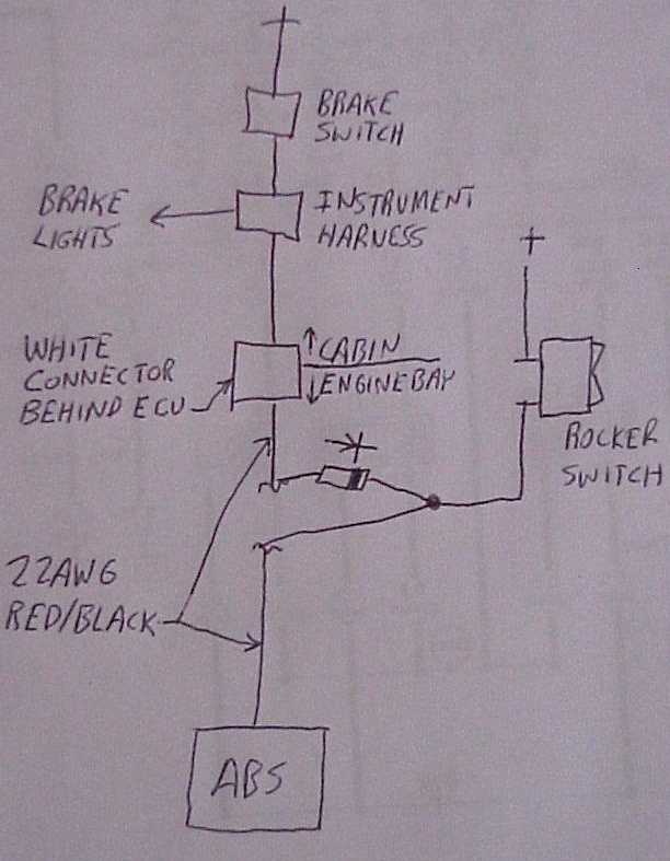
Caution: under some conditions this may cause the ECU to dump power into to your brakes while EDL is active! Consider disabling ESP entirely if you want to do this; i.e. wire pin 76 (grey/yellow) of the ABS controller to ground.[45]. Note that the pinout may vary depending on ESP version! Make sure you verify with a wiring diagram before doing any modifications.[46]
There is a second method, which involves tapping into the brake switch, but it is not recommended.
Disable MSR
MSR (Motor Slip Regulation) increases requested torque if the ESP/ABS controller detects wheel slippage due sudden decrease in engine RPM (torque braking), or detects that the engine is about to stall.
If you want to disable MSR:
- CWMSRCAN (11585) - set bit 0 to 1 (change from 0x02 to 0x03, or 0x07 to disable both MSR and slow path ASR via KLDMASRL). Note that this also disables engine stall protection!
If you want to disable MSR and both fast and slow ASR, set CWMSRCAN to 0x03 and all of NASNOTKL to 0xff, but see note above about automatic transmission protection.
Launch control
Soft Limiter
Very rudimentary "launch" control can be added via using two RPM limits[47][48]
- VNMX (1157E) - The vehicle speed for activating the raised (normal) rev limit. Set this as low at it goes (1.25 km/h) so the launch control shuts off as soon as you start moving off the line.
- DNMAXH (16304) - This is the RPM above rev limit when the fuel cut comes on. Tweaking this helps make more boost on the limiter. 50 RPM is a good start.
- ITNMXH (16308) - Dwell time under lower limit before activating the upper limit. Set to 0.
- NMAX (1630A) - Ends up being the launch RPM. 4500 is a good start.
- NMAXOG (16312) - This is the raised RPM limit which becomes the standard limit. Set to your desired redline.
- TMOTNMX (16316) - Coolant temp for activating raised (normal) rev limit. Set this at -48 so that you can rev past the low limit while car is warming up.
- TNMXH (1631A) - This is the time duration of the raised (normal) rev limit. Set this to its maximum value of 655.3500 seconds. In theory, this may trigger at some point, but nobody has reported such a thing yet.
Some ECU's need:
- CWNMAXMD (CWDNMAX?) (8-bit) - Codeword Drehzahlbegrenzung (Codeword for RPM limiter). Change from 0 to 1
Example bin based on stock binary.
Hard Limiter
NOTE: may burn coilpacks/ICMs/ECUs and melt cats, not to mention result in valvetrain damage. Implement at your own risk! Recommended only for track cars without cats, etc.
- KFTSRL - Set to zero at desired rpm limit, and stock at 40rpm below desired limit. You MUST edit axis data to have the minimum step at the rev limit so the ECU does not interpolate between redline and axis entry just below redline[49]
- FTOMIN - set to zero
- NMAX, NMAXOG - set to just above hard rev limit so we get throttle cut as well for safety
- DNMAXH - set to something small so fuel cut comes in early (just above throttle cut)
The hard limiter cannot be fully implemented for AL/NLS (anti-lag/no lift shift) by simply altering maps. In order to build (and hold) boost safely at a significantly lower RPM than hard redline, custom code has to be added to ME7 to detect clutch position and vehicle speed accordingly. [50] [51] [52]
While this (more invasive) method has been used with some success (and has been ported to other ME7 ecus[53]), there are still some features missing from the AL/NLS code floating around Nefmoto.[54] In particular
- AL/NLS should be disabled if the motor is not up to temp
- Misfire detection should be disabled during AL/NLS (to prevent possible DTC/limp from misfires)
- Knock detection should be disabled during AL/NLS (to prevent timing from being trimmed out)
Wheel speed sensor
If you have different wheel rolling diameters from stock, and you want to log the correct speed:
- AIMVM (0x12A56) - Number of speed pulses per m for signal normalization v
Gear detection
The ecu computes the gear (gangi) from the quotient N/V out of nmot_w and vfzg_w. To find the current gear, the ecu uses for each possible gear a min and a max quotient to compare the actual N/v against.
You have to update these quotients in order to map with the present gearbox/wheels. The thresholds are named NVQUOT1O (upper quotient for 1st gear), NVQUOT1U (lower quotient for 1st gear) up to NVQUOT6O, NVQUOT6U for 6th gear.
- NVQUOT1O (0x013BC2)
- NVQUOT1U (0x013BC4)
- NVQUOT2O (0x013BC6)
- NVQUOT2U (0x013BC8)
- NVQUOT3O (0x013BCA)
- NVQUOT3U (0x013BCC)
- NVQUOT4O (0x013BCE)
- NVQUOT4U (0x013BD0)
- NVQUOT5O (0x013BD2)
- NVQUOT5U (0x013BD4)
- NVQUOT6O (0x013BD6)
- NVQUOT6U (0x013BD8)
Mono O2 sensor
Define these as 16 bit (do not designate LoHi or LSB), output type will be Hex digits. Still under development - may not work properly
Delete B1
- 0x3C8BE
- 0x3C8D0
- 0x3E832
Original value will be 1A91, to replace with B2 input change to 1891.
Delete B2
- 0x3C8F0
- 0x3C902
- 0x3EA90
Original value will be 1891, to replace with B1 input change to 1A91.[55]
Larger displacement
- KISRM - Integrator coefficient for intake model (dynamic)
- KUMSRL - Conversion constant from MAF to relative charge
KISRM is , where z = number of cylinders, VH is displacement, Vs is intake volume from throttle plate to intake valve, and zkorr is a correction factor dependent on z.
- z=4, zkorr=0.90
- z=5, zkorr=0.92
- z=6, zkorr=0.95
- z>6, zkorr=1.00
KUMSRL is , where VH is displacement in liters.[56] Note that in WinOLS (and most likely all XDFs that define this map location), the precision of the "factor" attribute of the map is insufficient to properly describe KUMSRL, which is why the stock value appears to be off.
DTC disables
Missing Message from Instrument Cluster
If you see "18058 - Powertrain Data Bus: Missing Message from Instrument Cluster", and adjusting cluster adaptation channel 60 doesn't fix it:
- CW_CAN_R (0x12C7A and 0x12C7C) - CAN receive enable
For the M-box:
- 12C7A (applicable for softcoding 06611) 32--->0
- 12C7C (applicable for softcoding 06711) 36--->4 (Don't just 0 this or you remove ABS/ESP module reception from the ecu)
For the L-box you can't 0 these or you'll kill CAN reception/timeout monitoring for the TCU as well. Instead:
- 12C7A (applicable for softcoding 06651) 35--->3
- 12C7C (applicable for softcoding 06751) 37--->7
This will ensure CAN monitoring is still active for the TCU and ABS, but kill P1650 when running M or L-box software in the earlier Bosch equipped cars[57]
You should only need this for older clusters that can't be fixed by recoding them (i.e. they do not have CAN, only k-line).
ESKONF
ESKONF or Endstufen Konfig (power output configuration) refers to a group of 7 bytes in the 1.8t, and 13 bytes in the 2.7 flash. In short, these bytes tell the ECU which physical electrical outputs are attached in that particular file. Typically, it's located right above KFKHFM. When removing a component ESKONF is often required to disable circuit diagnosis. Without properly configuring the relevant bit pairs you will get DTCs (Malfunction in circuit, internal resistance too high, etc) due to the missing hardware. Leaving dead hardware attached may prevent these, but isn't necessary when properly coded out.
For those of you not versed in hex, a byte is comprised of 8 bits. A bit can be either a 0, or a 1. A bit pair is two bits. When put together large numbers can be conveyed much more concisely than writing them out in the traditional manner. A byte can have a value between 00, and FF, where each of the two letters/digits represents 4 bits. The corresponding binary is expressed as follows:
0000 0000 = 00
0000 0001 = 01
...
0001 0000 = 10
...
0000 1111 = 0F
...
1111 0000 = F0
...
1111 1110 = FE
1111 1111 = FF
Now, back to ESKONF. The ESKONF configuration for 4B0906018CH is shown below. For the rest of this section, this configuration is the one being referenced.
AA FF 00 30 FF F8 30
First thing, we break this down into the corresponding bit pairs.
Byte 0: AA = 10 10 10 10
Byte 1: FF = 11 11 11 11
Byte 2: 00 = 00 00 00 00
Byte 3: 30 = 00 11 00 00
Byte 4: FF = 11 11 11 11
Byte 5: F8 = 11 11 10 00
Byte 6: 30 = 00 11 00 00
Bit pair legend:
- 11 = SKIP, as in that component is not installed.
- 10 = SPECIAL TREATMENT. For all intents and purposes, we're going to ignore this.
- 00 = INSTALLED
Now each of the bit pairs represents an available component configuration. The legend for and layout of these components is available in the DEKON module of the FR, but I have broken it down for you here as well:
ME7.1 bit pairs
Byte  0: EV6    EV3     EV4     EV1
Byte  1: XX     NWS1    LULK    TEV
Byte  2: XX     EKP     AKF     XX
Byte  3: XX     XX      XX      SLP
Byte  4: EV5    SLV     XX      NWS2
Byte  5: HSH2   ULT     EV2     LDR
Byte  6: XX     BKV     HSH     XX
Byte  7: XX     XX      XX      XX
Byte  8: ZUE    ZUE     ZUE     ZUE
Byte  9: ZUE    ZUE     ZUE     ZUE
Byte 10: XX     XX      XX      XX
Byte 11: XX     XX      XX      XX
ME7.5 bit pairs
Byte 0: ZUE4   ZUE3   ZUE2   ZUE1
Byte 1: NC     NC     NC     NC
Byte 2: EV4    EV3    EV2    EV1
Byte 3: LSHHK  EFLA   SU/LDR TEV
Byte 4: BKV    NC     AAV    MIL
Byte 5: NC     NC     EKP    SLP
Byte 6: ULT    EAGR   SLV    NWS
Abbreviations
- XX: unknown/unused
- ZUE: Ignition coil
- NC: Not configured
- EV: Fuel injectors
- HSH/LSHHK: Rear O2 sensor heater
- MIL: Malfunction indicator lamp, OBD
- EFLA: Error lamp (non OBD compliant?)
- SU/LDR: N75 boost control solenoid
- TEV: N80 evap purge regulator valve
- AKF: V114 evap flap motor?
- LDP: Leak detection pump
- EAGR: EGR valve power amplifier
- BKV: Brake booster pump
- AAV: Shut off valve (Absperrventil vorhanden)
- EKP: J17 Fuel pump relay
- SLP: J299 SAI pump relay
- SLV: N112 SAI solenoid valve
- NWS: N205/N208 Camshaft timing control/VVT
- ULT/LDUVS: N249 diverter valve (Schubumluftventil)
- LULK: N335 airbox flap (RS4)
So, back to our example. Byte 3:
0x30 = 00 11 00 00
Each bit pair represents a component. Being 00 means that particular component is installed, while 11 means it isn't.
The bit pairs for Byte 3 are as follows:
LSHHK EFLA LDR TEV
This translates into the following configuration:
- LSHHK: Rear 02 sensor
- EFLA: Not installed
- LDR: N75
- TEV: N80
If we wanted to remove any of these, we'd change the corresponding bit pair from 00 to 11 and recalculate the total of the bits in order to convey the data as hex. Best bet, use a hex calculator for this part.
Example
You want to remove rear oxygen sensor diagnosis:
OLD Bit pair arrangement:
00 11 00 00 = 0x30
NEW Bit pair arrangement:
11 11 00 00 = 0xF0
So, to remove the rear 02 sensor ESKONF is changed from:
AA FF 00 30 FF F8 30
to
AA FF 00 F0 FF F8 30
Rear O2 Sensors
Rear O2 ESKONF
If you intend to disconnect/remove the sensors, the first thing to try is to configure ESKONF (13 bytes starting at 0x10C75):[58]. As a side benefit, even if you still intend to leave the sensors installed and connected, you should not need to disable circuit diagnosis.
- ESKONF[5] HSH2 (0x10C7A) - set to 0xC0 (set bits 6 and 7)
- ESKONF[6] HSH (0x10C7B) - set from 0xF3 to 0xFF (M-box) (set bits 2 and 3)
- ESKONF[6] HSH (0x10C7B) - set from 0xC3 to 0xCF (L-box) (set bits 2 and 3)
Cat DTCs
If that does not work (it should), you can set these to zero to disable rear cat DTC entirely (but you may not pass emissions if you do this):
- CDKAT - Cat diagnosis in OBDII-Mode. (ME7.5 vehicles containing CDKATSP AND SPF should 0 these as well).
- CWDLSAHK (0x18663) - Code word for probe aging after KAT[59] (not needed if you set CDLASH to 0)
Readiness thresholds
To try to pass readiness w/o changing ESKONF or disabling DTCs, you can try setting the SRY thresholds to zero: [60][61]
- SRYAGR (0x810974) - Threshold for Readiness formation EGR diagnosis (unused)
- SRYHS (0x810975) - Threshold for Readiness formation O2 sensor heating diagnosis (ready bit 6)
- SRYKAT (0x810976) - Threshold for Readiness formation catalyst diagnosis (ready bit 0)
- SRYLS (0x810977) - Threshold for Readiness formation lambda sensor diagnosis (ready bit 5)
- SRYSLS (0x810978) - Threshold for Readiness formation SAI diagnosis (ready bit 3)
- SRYTES (0x810979) - Threshold for Readiness formation canister purge diagnosis (ready bit 2)
If you have removed precats and relocated your rear O2s, and you want to keep the sensors in place and working (to make sure you still pass emissions testing), you may throw an efficiency code. You maybe able to numb ME7's sensitivity (note: untested) via AHK: [62][63]
- AHKATMN (0x18672) - leave alone
- AHKATMX (0x18673) - set to max
- AHKATS (0x18674) - set to max
- AHKATSB (0x18675) - set to max
Cat and O2 complete removal and DTCs
If you want to remove your rear O2s and cat entirely, and ESKONF alone does not work, set these to zero:[64]
- CDHSH = 0 - Post cat O2 heater diagnosis
- CDHSHE = 0 - Post cat O2 heater amplifier diagnosis
- CDLATV = 0 - Lambda sensor aging diagnosis (tv) in OBDII-Mode (inverse: EURO-Mode)
- CDLASH = 0 - Lambda sensor aging diagnosis (SHK) in OBDII-Mode (inverse: EURO-Mode)
- CDLSH = 0 - Post cat O2 sensor diagnosis (see note below about ME7.1.1 and ST10)
- CDLSHV = 0 - Lambda sensor sensor interchange recognition (N/A for vehicles equipped with a single post cat sensor, IE 1.8t and certain vr6)
- CWKONABG (0x181B9)
- CWKONABG.0 = 0 - for ME7.1, ME7.1.1, B5 A4 & TT ME7.5
- CWKONABG.0 = 1 - for B6, B7, Exeo etc. ME7.5
- CWKONLS (0x181BB) - Vehicles with 4 installed sensors (2 banks) - change from 51 (0x33/00110011b) to 17 (0x11/00010001b)[65] Vehicles with 2 installed sensors (one bank) (default value 3), set to 1. When setting CWKONLS CDLSH must also be configured to prevent malfunction in circuit DTC's.
- CWKONLS.1 = 0
- CWKONLS.5 = 0
For ME7.1.1 ST10 ECUs these may not work for you.[66] Instead:
- CDLSH.0 = 1 (not all zero!)
- USMIN = -1
- TANHKMMN = -273
- THSHA = 0
- TRSE = 0
Finer grained control
Change these to disable rear O2 lambda control:[67][68]
- CLRHK (0x11A87) - Code word for Lambda - Bit 0 is Control post cat on/off. Set bit 2 and 0, clear bit 3 to disable; i.e. set from 72 (0x48/01001000b) to 5 (00000101b)[69]
- CLRHK.0 = 1
- CLRHK.2 = 1
- CLRHK.3 = 0
- CLRHK.6 = 0 (don't care)
- CLRSHK - Wideband vehicles use CLRSHK. In these the default value is typically 16 (0x10/0001000b). Set bit 0 (and possibly set bit 2 and clear bit 3?) to disable (set to 5?)
- CLRSHK.0 = 1
- CLRSHK.2 = 1(?) unconfirmed.
- CLRSHK.3 = 0(?) unconfirmed.
- CLRKA (0x11A72) - set to 0[70]
You can test readiness by using VCDS/VAGCOM[71]
To fix up the catalyst temperature model (if you are running no precats):
ATM:
- ZATMIKML = 1
- ZATMIKKML = 1
- TABGMEX = F(max)
- TIKATMOE = 0
- ZATMKML = 1
- ZATMKKML = 1
- TKATMOE = 0
(above maps can be skipped IF diagnostic functions DLSH, DLSAHK, DHLSHK, DSLSLRS, DKATLRS are disabled AND LAMBTS, LRSKA, BBSAWE, LRSHK are fixed as shown further down. But personally I would set these maps anyway to do a *proper fix*, so even me7 logger would log tkatm_w = tikatm_w = tabgm)
- TKATW = F(max)
LAMBTS (1. use temperature in exhaust manifold for BTS enrichment instead of precat 2. Enable LAMBTS only on high exhaust manifold temperatures - ignore cat/precat temperatures):
- CWLAMBTS.2 = 1
- DTBTS = 0
- TKATBTS = F(max)
- TIKATBTS = F(max)
LRSHK (to disable postcat o2 correction):
- CLRSHK.0 = 1
- CLRSHK.1 = 1
LRSKA (to disable "cat cleaning" function; can mess with idle lambda target):
- CLRSKA.0 = 0
BBSAWE (1. disable unneeded cat related cut-off latency 2. Do not disable cut-off based on cat temp)
- KFTVSAKAT = 0
- TKATSA = F(max)
You should not have to touch these, but are are included for completeness:
- CLAHSH - Error Class: Bank 1 post cat O2 sensor heater
- CLAHSH2 - Error Class: Bank 2 post cat O2 sensor heater
- CLAHSHE - Error Class: Bank 1 post cat O2 sensor heater amplifier
- CLAHSHE2 - Error Class: Bank 2 post cat O2 sensor heater amplifier
- CLALSH (0x10717) - Error Class: Lambda Probe post Kat Bank 1: set to 0
- CLALSH2 (0x10718) - Error Class: Lambda Probe Post Kat Bank 2: set to 0[72]
- CLRHKA (0x19FCF) - Code word for Lambda - Control post cat: set to 1? (original value 0)[73]
EGT
Removal
If you want to disable your EGT sensors:[74] (Note that my old M-box xdf is wrong[75] for CDATR/ATS. Please use these offsets.)
- CDATR (0x18196) - Configuration byte diagnosis exhaust gas temperature regulation
- CDATS (0x18197) - Configuration byte diagnosis exhaust gas temperature sensor
- CATR (0x192CA) - Configuration byte exhaust gas temperature regulation (disables ATR)[76][77][78]
Alternately, setting both of these to their maximum (1229) may help: [79]
- TABGSS (0x1C514) and TABGSS2 (0x1C516) - Desired exhaust gas temperature for EGT regulation
You shouldn't have to touch these, but are included here for completeness:
- CLAATR - Error class exhaust gas temperature regulation
- CLAATR2 - Error class exhaust gas temperature regulation bank 2
- CLAATS - Error class exhaust gas temperature sensor
- CLAATS2 - Error class exhaust gas temperature sensor bank 2
Wideband EGT sensor swap
You can also swap to RS6 sensors to read an extended range (-40C to 1110C),[80] in which case you will have to change:
- TABGTA (0x1C4DE)
- DTPATS (0x192F0)
- TATSMN
- TATSMX
Part numbers are
- Bank one - 077 919 529E
- Bank two - 077 919 529D
- Both - 077 998 124
Secondary Air Injection
Note: 6sp S4s do not have SAI, so this only applies to S4 tip cars. Locations, if noted, are applicable to L-box ONLY.
There are 2 generally accepted ways to disable SAI DTCs:
The first method sets the monitor to unsupported (falsely shown as PASSED in VCDS):
- CDSLS to 0
- CWKONABG bit 2 to 0 (e.g. change from 5 to 1).
However, if your SAI pump is dead or failing, it will cause cold start issues.[81] In addition, it will only show SAI unsupported, and NOT truly passed. To fix this, unplug the pump from the relay and modify
- MSLUB (0x1A698)
- MSLBAS (0x183CC)
The values in this table are calculated airflow for a given battery voltage and are displayed in kg/h. To disable (or rather fool the ecu into accepting no flow as normal) you must set these values to 0.[82][83] It will also have the happy side effect of causing the readiness tests to actually run and pass.
You can also try setting
- FHOKH to FF FF
If you choose this method, make sure to set CDSLS and CWKONABG back to stock.[84]
If you wish to remove the relay completely as well, you must also disable circuit diagnosis in ESKONF by setting the appropriate bitpairs SLV (N112) and SLP (J299) to 11 and possibly also set CWKONABG to 0.[85]
Evaporation
- ESKONF[2] AKF (0x10C77) - set from 0xE3 to 0xEF (M-box) (set bits 2 and 3)
- CDLDP - Eurobyte - LDP Diagnosis
- CDTES - Eurobyte - EVAP diagnosis
- CLATEVE - EVAP plug
- CLALDPE - LDP plug
Catalyst Heating
- FKHABMN (0x1937D) - set to 0 if you do not have cats.
You can also try
- FHOKH - set to FF FF
Additional Reading
- Tony@NefMoto's website - one stop shopping for real tuning discussions, without the glass bead trading game and secret handshakes.
- Motronic abbreviations
- VCDS
- Lemmiwinks
- Basic tuning guide - caution: this is only an example
References
- ↑ Hex editing the Galletto executable to work with other FTDI based cables
- ↑ Hex editing the Galletto executable to work with other FTDI based cables
- ↑ Using MProg to recode a USB/KKL cable
- ↑ Nefmoto flashing software
- ↑ VisualME7Logger on GitHub
- ↑ VisualME7Logger thread
- ↑ Allow logging start before motor is running
- ↑ Theoretical KRKTE calculation
- ↑ Nefmoto discussion about incorrect KRKTE map pack scaling
- ↑ 5120 hack
- ↑ MAF scaling when MLOFS!=0
- ↑ Working around the ps_w limit with KFLF
- ↑ Nefmoto injector scaling discussion
- ↑ EV14 TVUB starting point
- ↑ EV14 TEMIN, KFBACKL, KFVACKL adjustments
- ↑ EV14 KFFWL adjustments
- ↑ EV14 KFFWL adjustments followup
- ↑ Mysterious LAMFA axis values
- ↑ Effect of ZKLAMFAW on LAMFA
- ↑ Effect of ZKLAMFAW
- ↑ Analysis of CWLAMFAW bit 0
- ↑ Calculation of lamfawkr
- ↑ Nefmoto BTS discussion
- ↑ KFDLBTS vs DLBTS
- ↑ disabling LTFTs
- ↑ disabling LTFTs
- ↑ Nefmoto FKVA discussion
- ↑ Using KFLDHBN instead of LDRXN to determine boost request
- ↑ KFVPDKSD/E and WDKUGDN throttle tuning near wg cracking pressure
- ↑ Calibrate KFLDRL using KFLDAPP
- ↑ P1556/P1557 incorrectly reported by VCDS?
- ↑ P0234 incorrectly reported by VCDS?
- ↑ negative and positive deviation swapped
- ↑ Getting around the ME7 boost limit
- ↑ Tuning KFMIOP properly
- ↑ KFMIOP load axis is shared by KFZWOP and KFMDS
- ↑ How to disable torque monitoring
- ↑ Diagnosing sources of torque intervention
- ↑ Disabling ARMD (anti-judder)
- ↑ Disabling ARMD (anti-judder)
- ↑ Nefmoto long term knock control adaptation discussion
- ↑ Dyno tuning VVT (NWS)
- ↑ Road log tuning VVT (NWS)
- ↑ Disable ASR but keep ABS
- ↑ Disabling ESP by grounding handbrake indication
- ↑ Different ESP versions for parking brake disable method
- ↑ Nefmoto launch control discussion
- ↑ Nefmoto launch control discussion
- ↑ hard rev limiter via cutting spark
- ↑ Nefmoto wiki: AL/NLS
- ↑ setzi: selectively cut spark to build boost
- ↑ Jason: add setzi's mod to Tony's S3 image
- ↑ Adding AL/NLS to various variants of ME7.X
- ↑ AL/NLS feature wishlist
- ↑ Mono O2 sensor
- ↑ KUMSRL/KUMSIRL
- ↑ Prevent P1650 DTC
- ↑ Using ESKONF to code out rear O2s
- ↑ Nefmoto emissions discussion
- ↑ Numb cat efficiency DTC via SRY
- ↑ Numb cat efficiency DTC
- ↑ Numb cat efficiency DTC
- ↑ Numb cat efficiency DTC via AHK
- ↑ Nefmoto rear O2 delete discussion
- ↑ Rear O2 codeout summary
- ↑ Nefmoto rear O2 ME7.1.1 ST10 delete
- ↑ How works secondary O2 lambda control
- ↑ Nefmoto rear O2 lambda control discussion
- ↑ CLRHK analysis
- ↑ Rear O2 disable lamka
- ↑ Readiness using VCDS
- ↑ Nefmoto rear O2 lambda control discussion
- ↑ CLRHKA change not needed
- ↑ EGT sensor removal
- ↑ EGT sensor removal
- ↑ Leaving EGTs in open air
- ↑ Disable CATR to prevent 0.75 lambda protection when CDATR is disabled and EGTs are removed
- ↑ ATR vs BTS
- ↑ Nefmoto discussion of EGT temp limits and sensor removal
- ↑ Using RS6 EGT wideband sensors
- ↑ SAI cold start problems
- ↑ Disabling SAI through MSLUB
- ↑ Disabling SAI through MSLBAS
- ↑ Zeroing MSLUB/MSLBAS
- ↑ Complete SAI removal