Tip To 6spd Conversion
Jump to navigation
Jump to search
Objective
Convert a Tip B5 S4 into a 6spd Manual
Special Tools
- Bentley Manuals
- VAG-COM e.g. Ross-Tech
- Engine Bridge
- Transmission Jack
- VAG 3213 Shaft Alignment Tool
- Which I will show you how to make yourself
- VAG 3242 Crank Shaft Lock Pin
- Connector pin removal tools
- Driveshaft star-pattern bits
- M17 Hex Allen Socket/Key
- Multimeter with continuity test
- Torque Wrench capable of 150 ft.lbs
- The usual collection of Metric Sockets, Wrench, Torx bits
Parts
Hardware
The actual part numbers you need may vary depending on what year/models you are mixing. The author takes no responsibility and will not answer any questions on parts. DO NOT assume these are the correct or only parts you will need.
- 6spd EDU Transmission (01E300048S)
- RS4 Transmission mounts or others
- Transmission mounting bracket (Left 8D0399107S, Right 8D0399108AN)
- Mounting Bracket Heat shields (Left 8D0399299C, Right 8D099300M)
- Starter Mounting Bolt & Nut (N10431702, N10261304)
- Most Bell housing bolts can be reused, but some are different (N90767202, N90495604, N10238202)
- Left (8D0407271AR/8D0407451MX) & Right (8D0407272AR/8D0407452KX) Front Axles
- 2pcs Axle CV Sealing washers (8D0407309A)
- CV Joint Bolts (12pcs N90668201) & Plates (6pcs 443407357/1K0407357D)
- 2pcs M16 Axle Bolts (4A0407643A)
- Right Axle Heat Shield (4D0407720)(Left side can be reused from Tip trans)
- May need two CV Boot kits if the axles were old and the boots look old / worn / about to tear
- Propshaft (8D0521101J)
- 2 x 6pcs New CV Joint Bolts (N0199261)
- Manual Transmission to Propshaft Heat Shield (8D0301325B) and Heat Shield mounting bolts (2pcs N10425101)
- 2pcs Axle CV Sealing washers (183521141A)
- Rear Differential (01H500040N DXT)
- 2 x 6pcs New CV Axle Bolts (N90668201) (I was able to re-use tip ones)
- 2pcs Axle CV Sealing washers (8D0407309A)
- Shift box (8D0711026B & 8D0711167) with shifter mechanism
- Selector Shaft Rod & Armature (8D0711151J) with Selector Lever & Knuckle joint, Torque Bar (8D0711271N)
- Black Trim plate for Manual Transmission (8D0864261H6DP)
- Retaining frame (8D0863279K, 8D0864281H)
- Shift Sound absorber (8D0711406D)
- Manual Foot Pedal assembly
- Clutch Master Cylinder (8E1721401AG)
- Clutch Master to Slave line (8E1721465J)
- Clutch Slave Cylinder (8E0721257B)
- Slave Mounting Bracket (8E0721487B)
- Brake Reservoir to Clutch Master Cylinder Line (857721453)
- Clutch (whatever ...)
- Guide Sleeve (01E141181A) and Guide Sleeve Bolts (3pcs N0402033)
- Clutch Bolts (6pcs N0147392)
- Rollout Bearing (012141165E) (Included with most new clutch kit)
- Dual Mass Flywheel (078105266M) or others
- Flywheel Bolts (8pcs N90705901)
- Needle Shaft Bearing (034105313A) (Included with most new flywheel)
- Turbine to DP Gasket (8D0253115F)
- Subframe Bolts (N90956801 4pcs)
- Always replace stretch bolts with newer x120mm bolts
Electrical
- Impulse Sender (Flywheel RPM Sensor) (06A906433C)
- Clutch Vent Valve Switch (811907343B) & Harness
- Clutch Position Sensor (Starter inhibitor switch 3B1911807A) & Harness
- Reverse Light Harness
Chemicals
- 6 x 120g packs of Audi CV Grease (G052133A3)
- Redline Moly Assembly Lube (for Needle shaft)
- Bucket & Mineral Spirits (for cleaning & washing CV Joints)
- DOT4 Brake Fluid e.g. Racing Blue (useful when bleeding brakes because new fluid is clearly blue)
- G12+ Coolant (But I prefer to filter and recycle mine)
- 2.5 liters Transmission Oil e.g. 1 bottle Redline MTL + 2 bottles MT-90
- 2 liters Differential Oil e.g. 2 bottles Redline 75w90NS
- Loctite (for sealing CV Bolts)
Optional
- Radiator for Manual Transmission (8D0121251AP)
- 6spd one has more cooling capacity, no built in ATF Warmer
- Never install a used radiator - always buy NEW !
- Subframe Brace 8D0399403A Bolt N90630503 x2 Nut N02300411 x2
- Gaskets & Covers for 2nd'ary Air Injection
- I can supply these if you lack the custom fabrication skills
- A nice (not Tip Buttons) Steering Wheel
- RS4 Air Leather Steering wheel
- A Nice Shift Knob & Boot
- Rieger Napa Leather illuminated 6spd Shift Knob & Boot
- M/T-Box ECU & Hitachi MAF (if using Bosch MAF)
- You may be ale to reuse your TIP ECU or Reflash it - I couldn't reuse mine
- Shifter Rod Rebuild Kit 8D0798151
- Shifter Rebuild Dampers 8D0711901A x2 C-Clip N0124121 Socket 8D0711279 Pivot Ball Joint Early Style 893711118E Late Style 8E0711118
- JHM Stabilizer Bushing
Process
Removal
Preparation
- Park with Handbrake-on
- Loosen wheel bolts now before the car leaves the ground
- Use M17 Socket & Breaker Bar to loosen Wheel Bolts
- Remove Wheel caps over the Axle bolts
- Use M16 Allen Key/Socket, a Breaker bar and Torque Multiplier (long extension) to loosen Axle bolt in Wheel
- Raise on Lift / Jackstands
Exterior
- Remove Headlights & Bumper, drain/store windshield washer fluid
- Drain Coolant
- Loosen Radiator and Drain Coolant
- Filter (e.g. using painters cheese-cloth or v.fine mesh filter) and store coolant for reuse
- Loosen Radiator and Drain Coolant
- Remove ATF system
- Drain ATF from Transmission
- Disconnect ATF lines to radiator and drain ATF
- Remove ATF Cooler from behind Left SMIC
- Optional : Remove Radiator
- Disconnect and remove Battery, store safely out of the way
- Remove Exhaust
- Disconnect entire Exhaust & Mufflers, and store out of the way
- Unbolt and Remove Downpipes from Turbine Outlets (4x 17mm/Side)
- Remove Propshaft
- Remove Heat Shields (2x T45)
- Unbolt CV Joints and disconnect (12x 6mm Allen & 2x 13mm center support)
- Remove Rear Diff
- Support Rear Differential
- Unbolt Rear axles to Diff (6x M10/Side)
- Remove Rear Differential
- Unbolt Torque Converter - Drive Plate
- Remove Engine Airbox, MAF, intake pipes, PCV and spider hose
- Remove 2nd'ary Air Injection
- Remove Pump
- Remove AIR Valves
- Remove EGT Sensors
- Remove EGT Sensor mounting plate, disconnect Vacuum lines and AIR Vacuum Valve, discard
- Reinstall EGT Sensors using a locking screw
- Seal off the vacuum line coming from the fuel rail assembly
- Support Engine motor with Engine Bridge
- Disconnect Heater to Engine Coolant lines if using an Engine Hoist or Crane
- Unbolt Front Axles (6x M10 Triple Square/Side)
- Unbolt Sub-frame
- Unbolt and set aside lower control arm and control link
- Unbolt engine mounts
- Unbolt and remove front sway bar / mounts assembly
- Store SubFrame and SwayBar assembly in safe place out of the way
- Disconnect and remove Automatic Transmission
- Unbolt Torque Converter from Drive Plate - As per Bentley (3x T55)
- Disconnect Shift selector cable
- Unbolt Starter and Trans to bell housing
- Remove bolts from Shift Box
- Unbolt Drive Plate / Starter ring
- As per Bentley
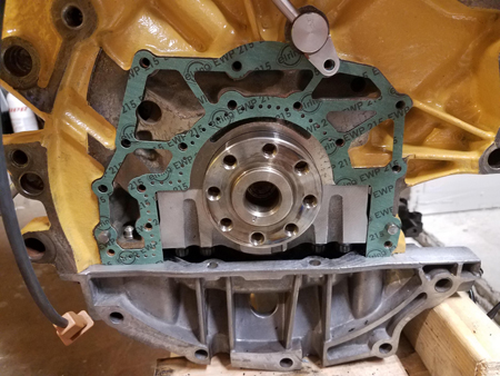
- Remove Hub from Crank Shaft
- The Spacer Hub is on the end of the Crank shaft to allow for the thinner drive plate and no flywheel
- NEEDS PIC
- The Spacer Hub is pressed onto the crank shaft flange, it can be removed using a Pulley Puller or Use a large flathead screwdriver working gradually around the perimeter, being careful not to damage the rear main seal.

Inside Cabin
- Remove Drivers side footwell covers
- Remove Left/Right footwell A-Pillar covers
- Remove Shifter Assembly
- Remove Shift Knob
- Remove Shift Trim
- Disconnect Tip harness cable and shift electronics board
- Remove Shifter mechanism
- Unbolt Shift Box and remove
- Disconnect Park-Ignition Interlock
- Remove Steering Wheel
- Remove Steering column trim pieces
- Disconnect clip holding cable inside ignition
- Cut Cable where it enters the Shifter assembly
- Remove the cable and discard
- File:Ignition.JPG
- Remove Pedals
- Reach behind brake pedal and unbolt pedal armature from Brake Master Cylinder
- Drain Brake Fluid from reservoir
- Loosen Brake Fluid Reservoir by disconnecting mounting bolt, detaching brake lines
- File:LiftBrakeReservoir.JPG
- Loosen 2 bolts holding Brake Vacuum reservoir onto firewall and pedal assembly
- Unbolt top of Pedal assembly from the footwell console frame
- Remove Accelerator Pedal from Pedal Assembly and store
- File:EmptyFootPedal.JPG
Installation
Installation is the reverse of remove ... <not>
- Replace Radiator with Manual one
- Process is as described in Bentley
- Remove Aux Fan Rail
- Unbolt A/C Condenser
- Pull securing plugs on top of radiator
- Wiggle out from the top, swap with the new one
- Refill Coolant, loosen bleeder screw to hasten the process
- Process is as described in Bentley
- Seal Secondary Air Injection
- Fabricate covering plates and seals
- File:SecondaryAirVentPlate.JPG
- Shifter Assembly
- Install Shift Box
- Bolt on from the top
- Attach Sound Absorber but don't torque nuts until Selector Rod is adjusted
- Shift Knob & Boot but don't install until Selector Rod is adjusted
- Clutch Line
- Clean out the line using compressed air
- File:ClutchLine.JPG
- Clutch line runs from back of the Master Cylinder through a hole in the firewall and back through another hole into the engine bay
- File:ClutchLineRouting1.JPG
- Then under the steering rack over the transmission bell housing
- File:ClutchLineRouting2.JPG
- Foot pedals
- There are a couple of different accelerator sensors depending on year, each with different connector/wiring. So if you purchase a 2nd-hand assembly remove the Accelerator pedal from it, and replace with your old Pedal & electronics
- Clutch Position Sensor must be aligned so that sensor just engages when clutch is fully depressed
- If not adjusted correctly the sensor will break when the clutch is pressed
- File:ClutchSensors.JPG
- Refill with Brake Fluid and bleed the Clutch
- Rear Diff
- Process is as described in Bentley
- Support the Diff on a Jack, and raise
- Torque the supporting Bolts on rear frame, and the carrier on the front
- Apply fresh CV Grease as needed to Axle CV's, keep the securing flange holes clean
- Reattach Rear Axles, torque the Axle CV to Flange bolts
- Process is as described in Bentley
- Flywheel
- Ensure the Adapter Hub on the end of the Crank shaft is removed before proceeding.
- When removed the face of the Crank Shaft Flange should be almost flush with the rear main seal
- Install a new needle bearing in FW
- Always use NEW Flywheel Bolts, torque to 44Ft.lbs, that's the easy part
- Always torque the bolts in a Star pattern, never do them sequential
- Get a Friend ready to help do the hard part : breaker bar + 180deg
- Rest of process is as described in Bentley
- Clutch
- Be careful not to get any grease on face of Flywheel or Clutch Friction plate
- Use the clutch alignment tool to center Friction Plate before Pressure Plate assembly is fastened
- Don't think you need to use new Fastening bolts, just re-tighten in star pattern
- Transmission
- Replace the Guide Sleeve, and lightly grease the outside with Red Moly
- Install new Push-Out Bearing
- Lightly (not much at all) grease the grooves at the end of the needle shaft, remove any excess grease, you don't want it to fling off onto the Flywheel & Clutch friction plate
- Install Mounting Brackets & Shields
- Install support RS4 Rubber Mounts
- Install Shift selector and torque rods onto
- Torque the selector lever onto selector shaft
- Select an even gear (2nd, 4th) by pulling the selector rod towards rear, listen for gear engaging
- When selecting even gear the selector lever should be almost horizontal, if not loosen selector shaft nut and adjust
- Now push the selector rod forward to select an odd gear (e.g. 1st, 3rd)
- When selecting even gear the selector lever should be almost vertical, it not loosen selector shaft nut and adjust
- Installing Slave Cylinder
- Lithium Grease on the body of the cylinder
- Grease on the end of the push shaft
- Install cylinder with mounting bracket, clip the clutch line into bracket
- Clip the clutch line into the slave cylinder, it should click, insert the retaining clip
- Installing Propshaft
- Same as Bentley
- Use the tool 3213 to hold the shaft straight before installing
- Support in the middle with jack and raise
- Bolt onto Rear Diff, 40 ft.lbs
- Align shaft center bearing with mounting holes
- Check the shaft is straight where it reaches the transmission
- If not, the engine is mounted crooked
- Loosen Engine Mount Bolts and Transmission Mount
- Use Crowbar to adjust Engine position until Flange on the end of Trans lines up with Propshaft
- Drain and Refill the Transmission and Diff's with new Fluid
- If EDU trans has two drain plugs, undo both, and refill to the filler plug line (not 7mm below)
- Adjust Shift Rods
- In case selector shaft comes loose while adjust its better to do this before Axles are installed
- Leave Torque Rod screw loose
- Tighten Selector Shaft screw, find Neutral, loosen screw and adjust until Neutral is centered, retighten
- Shift should be centered when in neutral, spring resistance should be felt moving left into 1st and right into 5th
- Make sure can select 1st thru 5th. Then adjust Torque Rod to center position after ensuring can also select Reverse
- Downpipes
- Use new Turbine-Exhaust Gaskets
- Exhaust
- Re-install Heat Shields first
- Attachment is the reverse of installation
- Front Axles
- Ensure CV joints are well greased with fresh CV grease
- If the axles are old and CV joints are stiff you can try cleaning and repacking with new grease
- Use Axle Bolt to loosen CV, remove boot, remove balls
- Be sure to clean off dirt/contamination with mineral spirits
- Repack with new grease
- Same process as replacing CV Boot
- If the axles are old and CV joints are stiff you can try cleaning and repacking with new grease
- Loosely install Axle bolts hand tight, they will be torqued when the car is on the ground
- Axle Heat Shields
- Ensure CV joints are well greased with fresh CV grease
- Bleed brakes
- Follow Bentley process
- Use Racing Blue so its easier to tell when fresh fluid is running thru whole lines
- Wheels
- Install wheel bolts hand tight
Lower Car to the ground
- Axle Bolts
- Use M16 Allen Key/Socket and torque to 140 ft.lbs + 180deg with breaker bar + extension
- Refill Coolant
Q: What you get for all this effort ? A: An extra pedal to depress
Electrical Harness
- Clutch Vent Valve to ECU, 2 wire connector (disables Cruise Control when clutch is depressed)
- Connect one wire to pin 3 of the 4pin Brake Light Switch over the Brake Pedal
- Run the other lead up through footwell and into engine bay plenum
- Connect to Pin 39 on the ECU connector, as shown here, connected to the yellow wire
- File:ECUHarness.JPG
- Clutch Position Sensor to Central Locking, 2 wire connector (disables starter until clutch is depressed)
- Connect one wire to ground
- Pull out pin 2 from the Blue Connector in Engine Bay Plenum
- Connect clutch sensor lead to Pin 2
- File:ECUConnectorPlenum.JPG
- Reverse Light, 2 wire connector on Transmission Right Side
- Buy/make a harness using 2-pin connector
- Run the harness up to grommet in the firewall next to O2 sensor brackets, and through the firewall to the ECU Box grommet
- Left A-Pillar Brown connector Pin 8 Blue/Red wire, cut-off old lead and splice-in new wire to Reverse Sensor
- File:ReverseLight.JPG
- Disconnect TCU Harness
- Pull passenger footwell
- Remove TCU from housing and disconnect
- Disconnect Brown 15 pin plug in right lower a-pillar, this connects the CAN bus and K-line to TCU
- Pull passenger footwell
- Remove the TCU to Transmission Valve Body and Range Selector harnesses
- Remove brackets holding cable along side of left wheel well
- Roll-up the cables and store safely where no electrical short-circuit
- Seal off the ends/connectors
Reprogramming
- Ignition on but no start
- Cluster
- Adaption, channel 60, set to 1025 (removes Transmission from CAN Bus)
- Ignition Off
- ABS
- Use Manual login code: 09495(based on state you will be recoding to)
- Recode to 6spd : 04395
- Ignition Off
- ECU
- If recoding a Tip ECU
- Login with 11463
- Recode to 6spd : 06711
- Ignition off
- Ignition back on
- Clear codes in Cluster, ABS, ECU
- ECU Throttle Body Adaption
- Set Block channel 60
Before Test Drive
- If oil was drained, pull Fuel Pump fuse, give the engine several 7s cranks, with 3s pause in between
- Reinstall FP fuse and fire it up
- Let the car idle to operating temp checking & refilling coolant
- Make sure you can select Reverse and the Reverse Light comes on
- If not dont force it, repeat the shift/torque rod adjustment process
- Instrument cluster will complain you need to depress Clutch before starting
- Starter inhibitor switch should prevent starting until clutch is fully depressed
- If Clutch Position Sensor is not correctly aligned, or not correctly connected to V94 then car will not start
When Test Drive is done
- After several miles return car to lift, recheck Trans fluid levels, adjust until fluid is 7mm below lip of the filler hole
Copyright
(c) Copyright 2009, the author aka "VR Life", all rights reserved. Contact the author VR's Email for any feedback, suggestions on this wiki.