Manifold air pressure: Difference between revisions
Jump to navigation
Jump to search
Content deleted Content added
No edit summary |
|||
| Line 9: | Line 9: | ||
voltage of 5 volts and earth. |
voltage of 5 volts and earth. |
||
The signal which the sender generates is a |
The signal which the sender generates is a |
||
pressure- |
pressure-proportional voltage ranging from 0 |
||
to 5 volts. |
to 5 volts. |
||
| Line 17: | Line 17: | ||
The Motronic also needs information on |
The Motronic also needs information on |
||
charge pressure so that it can take |
charge pressure so that it can take countermeasures if the maximum permissible |
||
measures if the maximum permissible |
|||
pressure is exceeded. |
pressure is exceeded. |
||
Revision as of 17:38, 10 October 2006
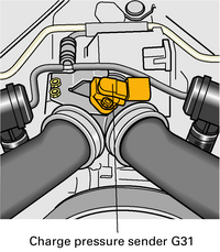
Charge pressure sender G31

The charge pressure sender is located upstream of the throttle valve control part.
The Motronic supplies the sender with a voltage of 5 volts and earth. The signal which the sender generates is a pressure-proportional voltage ranging from 0 to 5 volts.
At atmospheric pressure (at sea-level), the voltage is approx. 2.5 volts. The signal is used for charge pressure control.
The Motronic also needs information on charge pressure so that it can take countermeasures if the maximum permissible pressure is exceeded.
Substitute function and self-diagnosis
If sender G31 fails, the charge pressure is controlled via the characteristic curve (engine speed-dependent). This will result in a deficiency of engine power.