Boot mode: Difference between revisions
Jump to navigation
Jump to search
Content deleted Content added
No edit summary |
No edit summary |
||
| (2 intermediate revisions by the same user not shown) | |||
| Line 2: | Line 2: | ||
[[File:ME7.1.1-bootmode.png|thumb|400px|right|ME7.1.1]] |
[[File:ME7.1.1-bootmode.png|thumb|400px|right|ME7.1.1]] |
||
# With the ECU open and on the bench connected to your bench flash harness make sure the power supply is on, but the ignition switch is off (or whatever you use to simulate the ignition switch) |
# With the ECU open and on the bench connected to your bench flash harness make sure the power supply is on, but the ignition switch is off (or whatever you use to simulate the ignition switch) |
||
# |
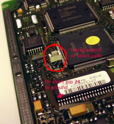
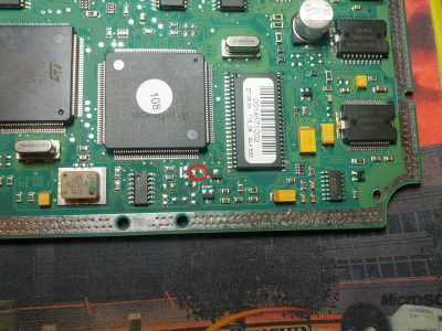
# Connect PIN 24 on the flash chip (800BB) to ground before turning on your switch/ignition signal. PIN 24 the the 2nd one in from the left side on the bottom. The chip when you're looking at it should have a circle in the top right hand corner (indicating PIN 1). Also the ECU's plugs will be facing to the RIGHT! Once you touch PIN 24 to ground, turn on the ignition switch and ''remove the ground from PIN 24 about 2-3 seconds later''. You are now in BOOT MODE. |
||
DO NOT leave this pin shorted to ground while you are programming the device; it will fail. It only has to be grounded while the ECU is "powering" up. |
DO NOT leave this pin shorted to ground while you are programming the device; it will fail. It only has to be grounded while the ECU is "powering" up. |
||
| Line 10: | Line 10: | ||
http://www.audizine.com/forum/showthread.php/269322-Tuning-your-Motronic-ECU-%28ME7.1%29?p=3465984&viewfull=1#post3465984 |
http://www.audizine.com/forum/showthread.php/269322-Tuning-your-Motronic-ECU-%28ME7.1%29?p=3465984&viewfull=1#post3465984 |
||
Grounding pin 24 on the flash also grounds the P0L.4 pin (Port 0, bit 4) on the CPU. The CPU samples this pin on power up. If it sees low, it will go into boot mode. |
|||
Latest revision as of 20:49, 21 September 2016


- With the ECU open and on the bench connected to your bench flash harness make sure the power supply is on, but the ignition switch is off (or whatever you use to simulate the ignition switch)
- Connect PIN 24 on the flash chip (800BB) to ground before turning on your switch/ignition signal. PIN 24 the the 2nd one in from the left side on the bottom. The chip when you're looking at it should have a circle in the top right hand corner (indicating PIN 1). Also the ECU's plugs will be facing to the RIGHT! Once you touch PIN 24 to ground, turn on the ignition switch and remove the ground from PIN 24 about 2-3 seconds later. You are now in BOOT MODE.
DO NOT leave this pin shorted to ground while you are programming the device; it will fail. It only has to be grounded while the ECU is "powering" up.
See also:
Grounding pin 24 on the flash also grounds the P0L.4 pin (Port 0, bit 4) on the CPU. The CPU samples this pin on power up. If it sees low, it will go into boot mode.