Manifold air pressure: Difference between revisions
m (→OEM) |
|||
| Line 77: | Line 77: | ||
*0 281 002 399: 0.2-2.5 bar (038 906 051 B - VW Golf V TDI) |
*0 281 002 399: 0.2-2.5 bar (038 906 051 B - VW Golf V TDI) |
||
*0 281 002 401: 0.2-3.0 bar (038 906 051 C - Audi TTMKII/VW Jetta V TDI) |
*0 281 002 401: 0.2-3.0 bar (038 906 051 C - Audi TTMKII/VW Jetta V TDI) |
||
*0 281 006 060: |
*0 281 006 060: 0.5-4.0 bar (03K 906 051) (uses characteristic curve type 2) |
||
===No temp sensor=== |
===No temp sensor=== |
||
Revision as of 08:00, 17 August 2014
"MAP" sensor in this context is a misnomer. The boost pressure sensor on the S4 is actually upstream of the throttle valve. The ECU itself simulates the pressure drop over the throttle plate to synthesize a calculated MAP pressure (in conjunction with MAF and RPM data, among other things). This also means that the data coming from this pressure sensor cannot be used to run in speed density mode w/o a MAF.
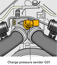
Charge pressure sender G31
The charge pressure sender is located upstream of the throttle valve control part.
The Motronic supplies the sender with a voltage of 5 volts and earth. The signal which the sender generates is a pressure-proportional voltage ranging from 0 to 5 volts.
At atmospheric pressure (14.7 psi or 1.01 bar at sea-level), the voltage is approx. 1.88 volts.
The signal is used for charge pressure control.
The Motronic also needs information on charge pressure so that it can take countermeasures if the maximum permissible pressure is exceeded.
The absolute maximum pressure reading is approximately 2.55996 bar absolute (22.45 psi), which should read approximately 4.76 volts. Pressure readings that deviate more than ~500mbar from specified pressure may cause throttle cut.
The maximum pressure reading is not a function of the MAP sensor, but rather the pressure representation limit in the ECU's memory (a 16 bit, unsigned integer).
Substitute function and self-diagnosis
If sender G31 fails, the charge pressure is controlled via the characteristic curve (engine speed-dependent). This will result in a deficiency of engine power.
Transfer function
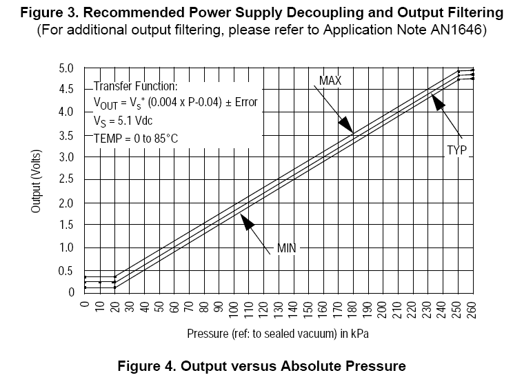
The G31 is part number 078 906 051 (Bosch 0 281 002 177) - similar to Bosch Motorsport 0 281 002 205 or Motorola/Freescale MPX4250A.
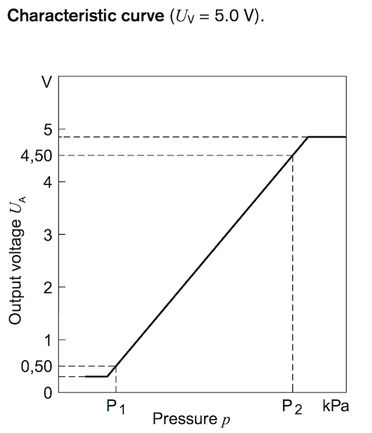
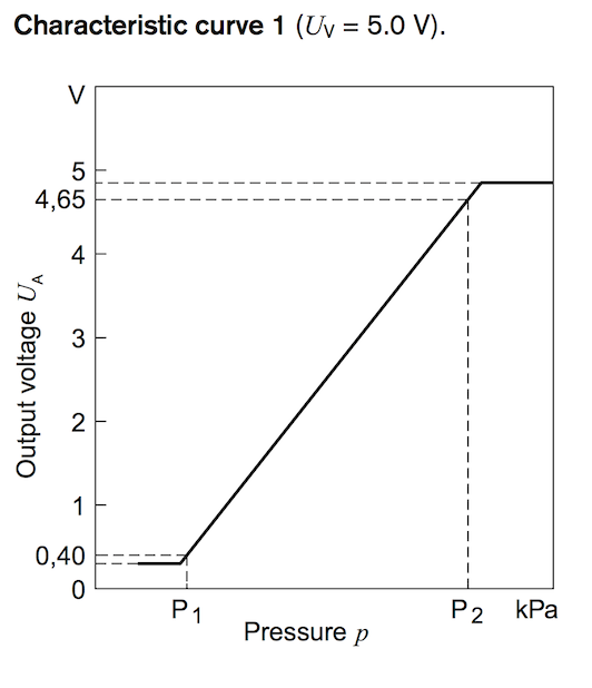
where P1 = 0.2 bar and P2 = 2.5 bar, such that
Gradient and Offset Calculations
From the calculations, we find the following for the stock MAP sensor (these are in accordance with the stock values in a file such as 551M):
DSLGRAD = 541.18
DSLOFS = -16.47
However, not all Bosch MAP sensors use the same transfer function. Another Bosch transfer function is shown here (type 2).

Ensure you are using the right characteristic curve to calculate the gradient and offset for the sensor.
Bosch
OEM
- 0 281 002 177: 0.2?-2.5 bar (078 906 051 - Audi 2.7t)
- 0 281 002 399: 0.2-2.5 bar (038 906 051 B - VW Golf V TDI)
- 0 281 002 401: 0.2-3.0 bar (038 906 051 C - Audi TTMKII/VW Jetta V TDI)
- 0 281 006 060: 0.5-4.0 bar (03K 906 051) (uses characteristic curve type 2)
No temp sensor
- 0 281 002 487: 0.2-2.5 bar (one mounting hole)
With temp sensor
- 0 281 002 399: 0.2-2.5 bar
- 0 281 002 205: 0.2-2.5 bar
- 0 261 230 042: 0.2-2.5 bar (one mounting hole)
- 0 281 002 573: 0.2-2.5 bar (no mounting holes)
- 0 281 002 437: 0.2-3.0 bar (one mounting hole)
- 0 261 230 105: 0.2-3.0 bar (one mounting hole)
- 0 281 002 244: 0.5-3.5 bar
- 0 281 002 456: 0.5-3.5 bar (one mounting hole) (uses characteristic curve type 2)
- 0 281 002 316: 0.5-4.0 bar
- 0 281 002 576: 0.5-4.0 bar (one mounting hole)
- 0 261 230 105: 0.2-3.0 bar (one mounting hole)
Motorola
MPX4250A
VOUT = VS (P × 0.004 - 0.04)
± (Pressure Error × Temp. Factor × 0.004 × VS)
VS = 5.1 V ± 0.25 VDC
References
- AW discussion on MAP sensor function


